
A kind of overlapping connection type stator core and preparation method thereof

The technology of a stator core and its manufacturing method is applied in the field of overlap-connected stator core and its preparation, which can solve problems such as magnetic flux leakage, reduction of motor efficiency, and blockage of electromagnetic field circuits, so as to reduce production costs, improve motor efficiency, and magnetic circuit Unobstructed effect

Active Publication Date: 2019-11-29
ZHEJIANG SPECIAL ELECTRIC MOTOR CO LTD
View PDF4 Cites 0 Cited by
  • Summary
  • Abstract
  • Description
  • Claims
  • Application Information

AI Technical Summary

Problems solved by technology

[0004] However, when the above-mentioned stator punches are stacked, the buffer grooves are aligned. After the linear yoke is bent into a ring shape, since the gaps on the stator punches of each layer are opposite to each other, after the buffer grooves are closed, an axially penetrating gap will be formed, resulting in an electromagnetic field. The circuit is blocked, resulting in serious magnetic flux leakage, thereby reducing the efficiency of the motor

Method used


Image

  • A kind of overlapping connection type stator core and preparation method thereof
  • A kind of overlapping connection type stator core and preparation method thereof
  • A kind of overlapping connection type stator core and preparation method thereof

Examples


Embodiment Construction

[0026] The present invention will be described in detail below in conjunction with the accompanying drawings and embodiments.

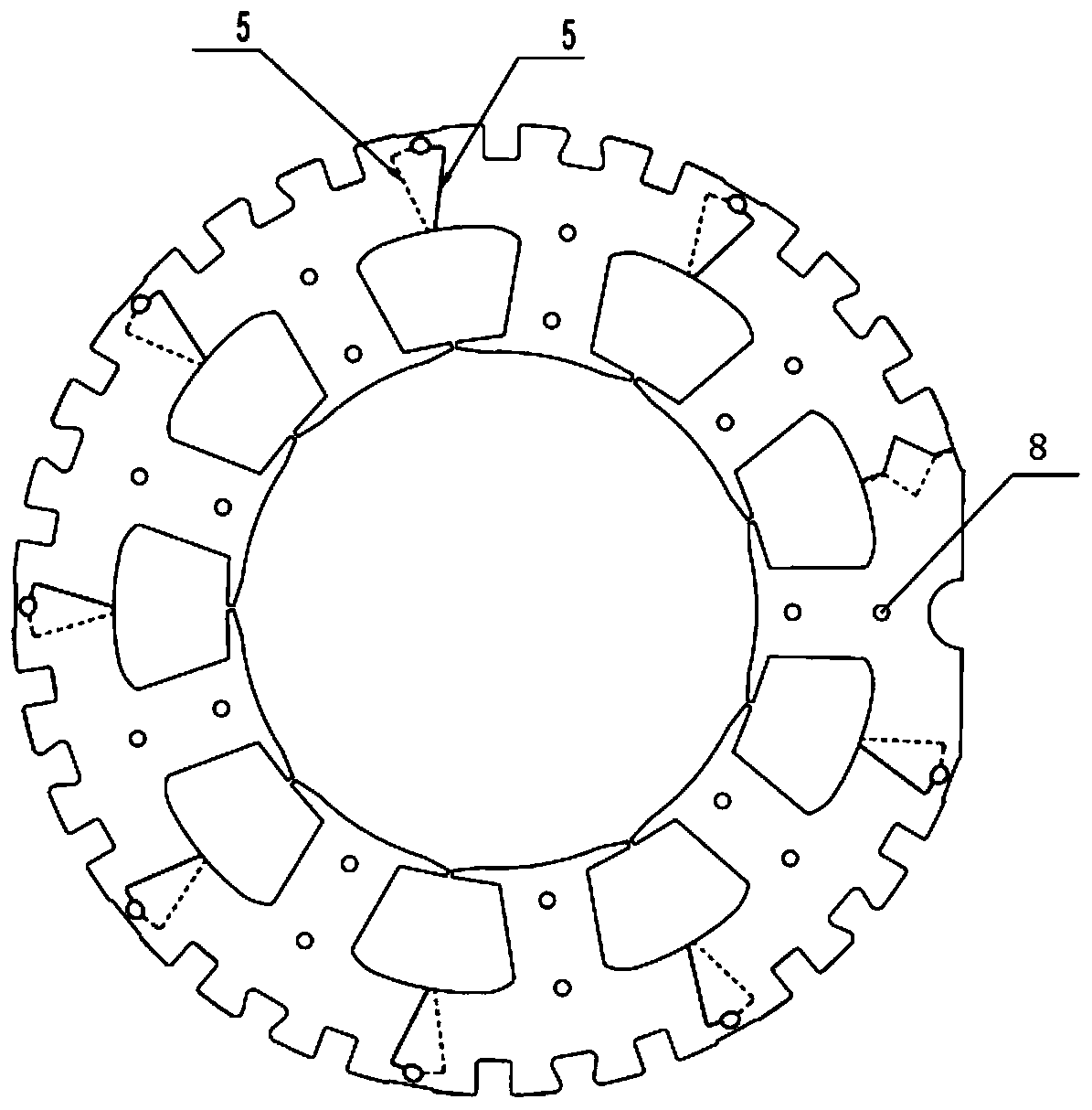
[0027] The stator iron core provided by the present invention is formed by interlacing two kinds of connected punching sheets which are inserted and sleeved; the seams of adjacent layers are not on the same axial section. Thus, while improving the performance of the motor, the material utilization rate is improved and the cost of the motor is reduced.

[0028] Figure 1-3 One embodiment of the connected lamination structure for the stator core of the present invention is shown. see figure 1 , the connected punching plate includes N punching units connected to each other through the connecting portion 4, the punching unit includes a yoke portion 1 and a tooth portion 2, and a stator slot 3 is formed between adjacent tooth portions 2. see figure 2 , after forming a loop, the adjacent yokes contact each other to form a seam 5, and the seams of adjac...


PUM


Abstract

The invention discloses a stator core. The stator core is characterized in that the stator core is formed by intersecting and overlapping first laminations and second laminations inserted and sleevedin pairs, wherein each of the first laminations and the second laminations comprises N lamination units which are mutually connected through connecting parts, each lamination unit comprises a yoke part and a tooth part, and a stator slot is formed between every two adjacent tooth parts; the mutual surfaces of the adjacnet yoke parts are contacted to form a seam after ring formation, and the seamson the adjacent layers are not on the same axial cross section; a buffer slot is formed between each seam and the corresponding connecting part, and each buffer slot is in the shape of a curve of which the curvature radius is 1.5 to 2.5 times of the thickness of the corresponding lamination. According to the stator core disclosed by the invention, the material utilization rate can be improved while the motor performance is improved. Moreover, automatic batch production is further facilitated, and the stator core is high in quality stability and small in electromagnetic noise.

Description

technical field [0001] The invention relates to the field of motors, in particular to a stator core for a motor, and more particularly to an overlap-connected stator core and a preparation method thereof. Background technique [0002] The stator core is one of the effective parts of the motor, and the manufacturing process of the stator core has a great influence on the operating performance of the motor. At present, the stator core of the motor is generally processed by integral stamping. However, this manufacturing method not only makes the utilization rate of iron core material low, but also the slot filling rate of the motor winding slot is not high, and due to the requirements of machine winding, the slot opening needs to be large, which affects the improvement of motor performance. [0003] The Chinese invention patent with the publication number of CN104753198A discloses a preset stator punching piece and a stator punching piece with it, a stator and a motor. An arc...

Claims


Application Information

Patent Timeline
Patent Type & Authority Patents(China)
IPC IPC(8): H02K1/14
CPCH02K1/14H02K2213/03
Inventor 张喜荣傅志华张伟青童永钢
Owner ZHEJIANG SPECIAL ELECTRIC MOTOR CO LTD
Learn More