
A waterproof and dustproof electromechanical equipment protective case

An electromechanical equipment, waterproof and dustproof technology, applied in electrical equipment shell/cabinet/drawer, electrical equipment structural parts, chassis/box/drawer parts, etc. Rain and dust problems, to achieve the effect of increasing fluidity, improving waterproof effect, and improving heat dissipation effect

Active Publication Date: 2020-06-16
CHONGQING VOCATIONAL COLLEGE OF TRANSPORTATION
View PDF7 Cites 0 Cited by
  • Summary
  • Abstract
  • Description
  • Claims
  • Application Information

AI Technical Summary

Problems solved by technology

[0004] The purpose of the present invention is to provide a waterproof and dustproof electromechanical device protective case, which can solve the problem that the existing protective case is easy to enter rainwater and dust, resulting in a short circuit of the electromechanical device

Method used


Image

  • A waterproof and dustproof electromechanical equipment protective case
  • A waterproof and dustproof electromechanical equipment protective case
  • A waterproof and dustproof electromechanical equipment protective case

Examples


Embodiment 1

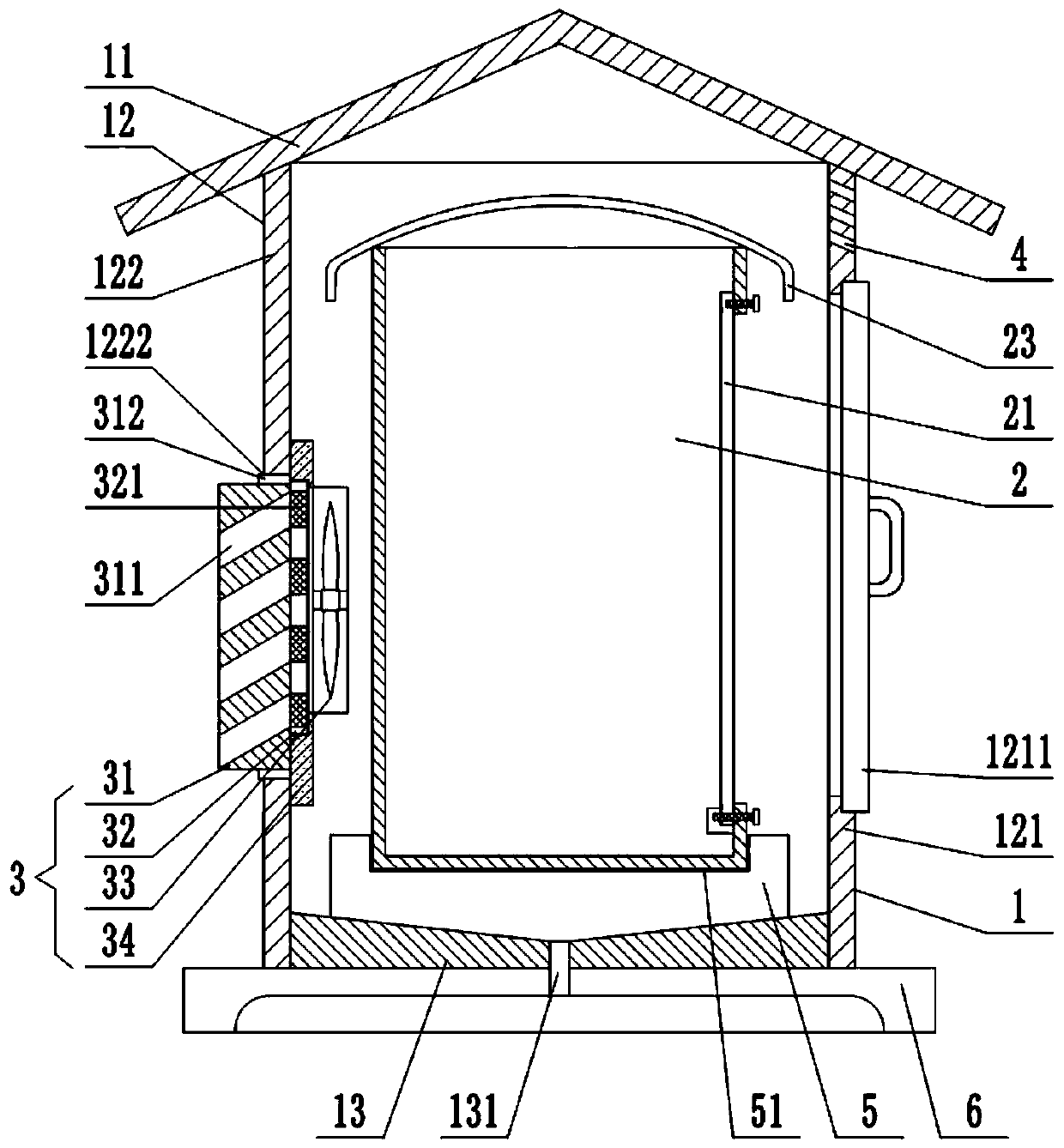
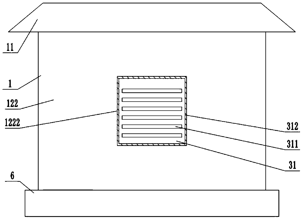
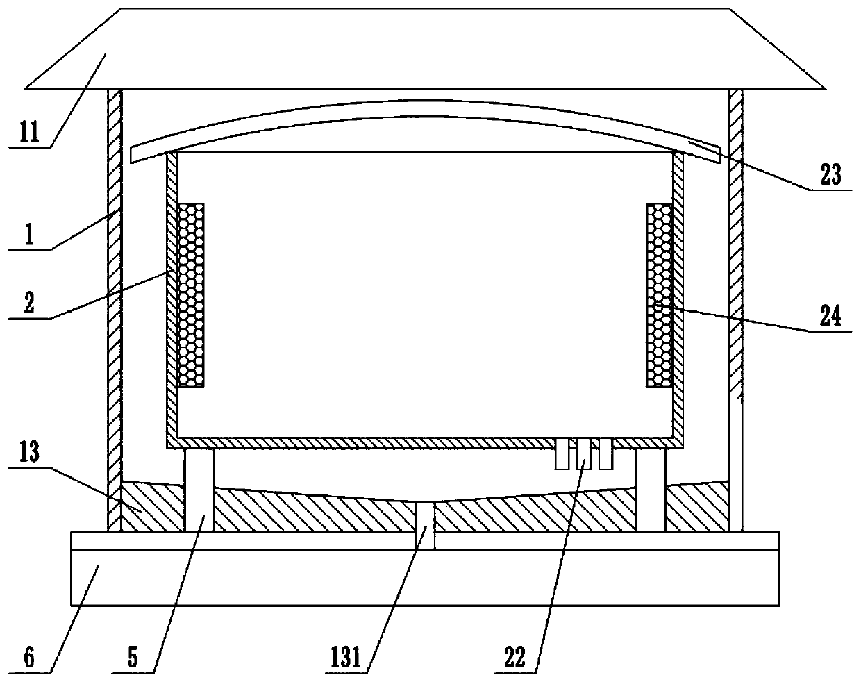
[0028] Such as figure 1 As shown, a waterproof and dustproof protective case for electromechanical equipment includes an outer box body 1 and an inner box body 2. The outer box body 1 includes a top cover 11, a side plate 12 and a bottom plate 13, and the side plate 12 includes a front side plate 121, Left side plate, right side plate, rear side plate 122, top cover 11 is slope roof shape, and front side plate 121 is provided with outer box door 1211, and outer box door 1211 is provided with handle; figure 2 As shown, the left side plate, the right side plate or the rear side plate 122 are provided with a through hole 1222. In this embodiment, the through hole 1222 is arranged on the rear side plate 122, and the through hole 1222 is provided with an air intake mechanism 3, and The wind mechanism 3 includes a ventilation plate 31, a dustproof plate 32 and an intake fan 33 arranged horizontally from the outside to the inside. The ventilation plate 31 is inserted in the through ...

Embodiment 2

[0035] Such as Figure 5 As shown, the difference between the present embodiment and the first embodiment is that a rain shield 7 is provided below the air inlet 311, and the rain shield 7 includes a rain holding part 71, an inclined part 72 and a sealing Live in the barrier part 73 of the air inlet 311, the middle part of the inclined part 72 is rotatably connected to the ventilation plate 31 through the pin shaft 76, the inclined part 72 rotates around the pin shaft 76 to drive the rain containing part 71 and the barrier part 73 to swing up and down, The barrier part 73 can seal the air inlet 311 when it swings upwards. In order to facilitate the barrier part 73 to swing and enter the air inlet 311 , a gap is provided at the lower part of the air inlet 311 .

[0036] When it rains, rainwater accumulates in the rain-holding part 71. Under the action of gravity of the accumulated water, the rain-holding part 71 swings downwards, and the inclined part 72 drives the barrier part...


PUM


Abstract

The invention belongs to the technical field of electromechanical equipment, and particularly discloses a waterproof and dustproof electromechanical equipment protective shell. The shell comprises anouter box body and an inner box body, wherein the outer box body comprises a top cover, side plates and a bottom plate; the side plates include a front side plate, a left side plate, a right side plate and a rear side plate; the left side plate, the right side plate or the rear side plate is provided with a through hole; an air inlet mechanism is arranged at the through hole; the air inlet mechanism comprises a ventilating plate, a dustproof plate and a fan which are sequentially and horizontally arranged from outside to inside; an air inlet is formed in the ventilating plate; the air inlet isinclined upwards; an air outlet is further formed in the outer box body; a water outlet is formed in the bottom plate; and the inner box body is a metal box. The protective shell is divided into theinner box body and the outer box body; the inner box body is the metal box, so that heat dissipation is facilitated; the air inlet mechanism is arranged on the outer box body, and a ventilation gap isformed between the inner box body and the outer box body, so that the flowability of air is conveniently improved, and the heat dissipation effect is improved; the air inlet is inclined upwards, so that rainwater does not easily enter the box; and the dustproof plate is arranged, so that the waterproof and dustproof effects are improved.

Description

technical field [0001] The invention belongs to the technical field of electromechanical equipment, and specifically discloses a waterproof and dustproof protection case for electromechanical equipment. Background technique [0002] With the continuous improvement of people's living standards, people's demand for electromechanical equipment in daily life is increasing. From transportation to various household appliances, computers, printers, etc., electromechanical products have become indispensable in people's life. Electromechanical equipment is a precision instrument. In order to ensure its normal operation and work in harsh outdoor environments such as temperature, humidity, solar radiation, wind, sand, and rain, it must be placed in a box or cabinet that can play a waterproof and dustproof role. etc. in a protective casing. [0003] Most of the protective casings of the current electromechanical equipment are single-layer metal sheets. In order to reduce the internal t...

Claims


Application Information

Patent Timeline
Patent Type & Authority Patents(China)
IPC IPC(8): H05K5/02H05K7/20
CPCH05K5/0213H05K5/0217H05K5/0234H05K7/20136H05K7/20181
Inventor 卢江林
Owner CHONGQING VOCATIONAL COLLEGE OF TRANSPORTATION
Learn More