Dual-beam staggered scanning method

An interlaced scanning and dual-beam technology, which is applied in the directions of acoustic wave diagnosis, infrasonic wave diagnosis, ultrasonic/sonic wave/infrasonic wave diagnosis, etc., can solve the problems of high arithmetic complexity and difficulty in adapting to fast imaging, and achieve the effect of frame rate improvement

Inactive Publication Date: 2019-02-19
珠海医凯电子科技有限公司
View PDF12 Cites 0 Cited by
  • Summary
  • Abstract
  • Description
  • Claims
  • Application Information

AI Technical Summary

Problems solved by technology

[0004] Chinese Patent Document No. CN102727256B discloses a dual-focus beamforming method and device based on a virtual array element. Through the virtual array element technology, the relevant effective information of multiple overlapping sound fields is extracted by using two time-delay superpositions. However, this technology requires Additional beamformers are required to achieve
[0005] Chinese Patent Document No. CN108309352A discloses a cosine transform domain ultrasonic imaging method. The echo signal is obtained by performing time-delay focusing on the received signals of each channel, and then the signal vector is obtained by calculating the sub-band signal and performing discrete cosine transform and other processing, and then each channel is obtained. The beamforming of scanning lines is used to improve image contrast and spatial resolution, but the implementation of this technology must rely on cosine transform processing, which has high arithmetic complexity and is difficult to adapt to fast imaging at high frame rates

Method used


Image

  • Dual-beam staggered scanning method
  • Dual-beam staggered scanning method
  • Dual-beam staggered scanning method

Examples


Embodiment Construction

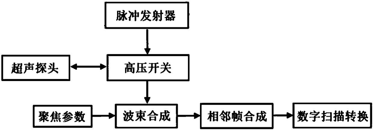
[0020] Such as figure 1 As shown, in this embodiment, the pulse transmitter outputs pulses to the high-voltage switch, and then the ultrasonic probe outputs and receives reflected echoes. During beamforming, a high-speed embedded chip is used to bias the multi-channel radio frequency echo signals.

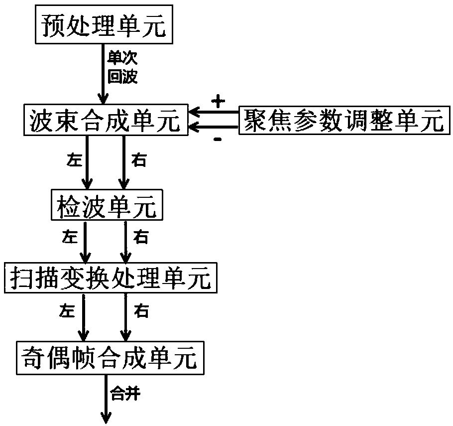
[0021] Such as figure 2 As shown, this embodiment specifically includes: a preprocessing unit, a beam synthesis unit, a focusing parameter adjustment unit, a wave detection unit, a scan conversion processing unit, and an odd-even frame synthesis unit, wherein: the preprocessing unit amplifies the echo signal and performs analog-to-digital conversion Then output to the beam forming unit, the beam forming unit performs bias beam forming according to the focusing parameters periodically output by the focusing parameter adjustment unit, and outputs the synthesized receiving beams to the detecting unit in turn for detection, and the scan conversion processing unit according to the dete...


PUM


Abstract

A dual-beam staggered scanning method includes the steps: receiving an array element array to obtain corresponding multi-channel radio frequency echo signals; performing offset beam synthesis to obtain a digital focusing image; combining two adjacent digital focusing images into an updated image to generate an image video B with higher definition or higher frame rate. According to the method, theresolution ratio can be remarkably improved through signal processing without any changing of existing hardware or the frame rate is remarkably improved under the same resolution ratio, and medical work is facilitated.

Description

technical field [0001] The invention relates to a technology in the field of ultrasonic image processing, in particular to an interlaced scanning double-beam method. Background technique [0002] The frame rate of ultrasound imaging technology depends on the detection depth, scan line spacing and number of shots. Existing technologies include increasing the frame rate by reducing the number of lines or by using multi-beams, but the realization of multi-beams needs to increase hardware resources and complexity, and increase system power consumption. [0003] The prior art includes a receiving method based on dual-beam and synthetic aperture as disclosed in Chinese Patent Document No. CN100450443C. After transmitting ultrasonic waves twice through the transmitter, the echo signals of each receiving array element on the same side relative to the transmitting center are selected. The beamformer generates the data of two half-beams; the two half-beam data are added together to o...

Claims


Application Information

Patent Timeline
Patent Type & Authority Applications(China)
IPC IPC(8): A61B8/00
CPCA61B8/4411A61B8/5207
Inventor 张国峰丁波朱逸斐
Owner 珠海医凯电子科技有限公司
Why Eureka
Try Eureka