Feeding and discharging device for numerical control cutting equipment

A technology for cutting equipment and feeding, applied in positioning devices, metal processing equipment, clamping, etc., can solve the problems of low automation and achieve the effect of preventing unstable fixing of pipe fittings

Active Publication Date: 2019-02-19
河南勤工机器人有限公司
View PDF10 Cites 6 Cited by
  • Summary
  • Abstract
  • Description
  • Claims
  • Application Information

AI Technical Summary

Problems solved by technology

[0003] Aiming at the deficiencies of the prior art, the present invention provides a loading and unloading device for CNC cutting equipment, which solves the problem of low automation in loading and unloading of existing cutting equipment

Method used


Image

  • Feeding and discharging device for numerical control cutting equipment
  • Feeding and discharging device for numerical control cutting equipment
  • Feeding and discharging device for numerical control cutting equipment

Examples


Embodiment Construction

[0029] In describing the present invention, it should be understood that the terms "longitudinal", "transverse", "upper", "lower", "front", "rear", "left", "right", "vertical", The orientations or positional relationships indicated by "horizontal", "top", "bottom", "inner", "outer", etc. are based on the orientations or positional relationships shown in the drawings, and are only for the convenience of describing the present invention, rather than indicating or It should not be construed as limiting the invention by implying that a referenced device or element must have a particular orientation, be constructed, and operate in a particular orientation.

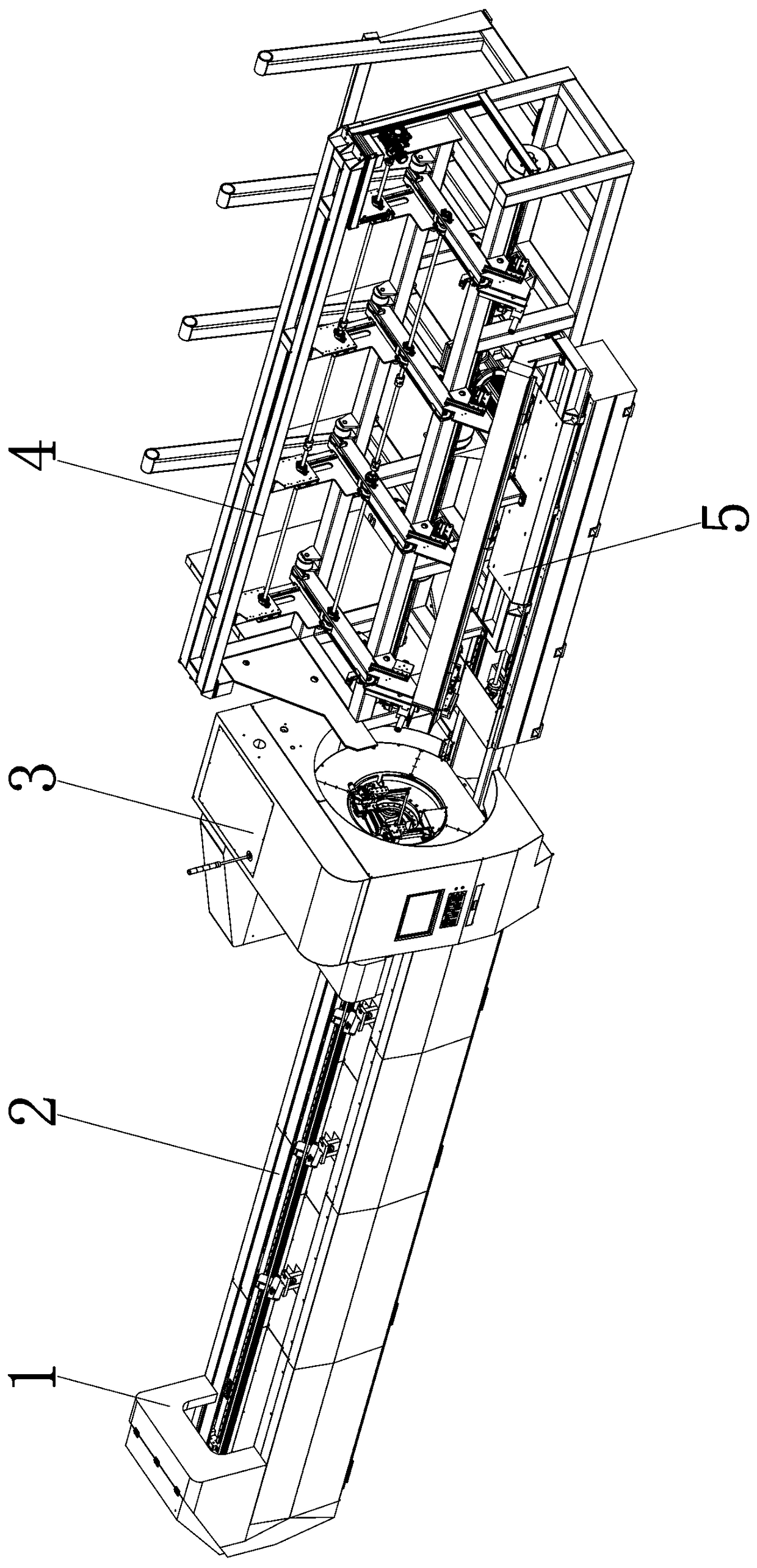
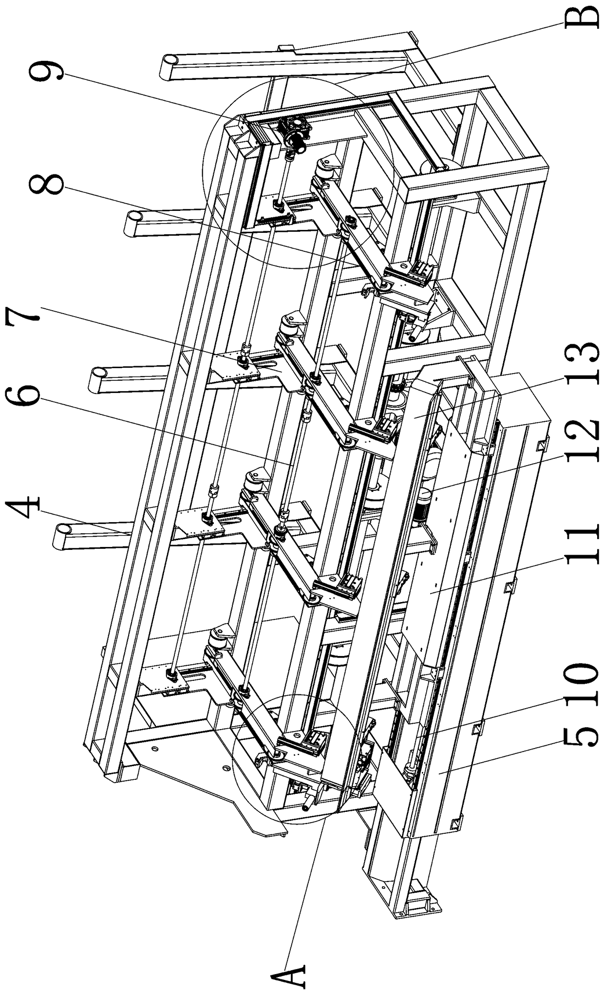
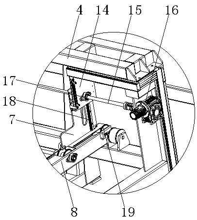
[0030]The technical scheme of the present invention is described in detail in conjunction with the accompanying drawings, a kind of feeding and unloading device for numerically controlled cutting equipment, including a feeding slide bed 2, a headstock 3, a feeding bracket 4 and a feeding bracket 5, and the upper rear side of the...


PUM


Abstract

The invention discloses a feeding and discharging device for numerical control cutting equipment. The feeding and discharging device comprises a supply sliding bed, a discharging support and a supplysupport; a fixed plate is fixed to the upper portion of the rear side of the discharging support; a pressing rotary shaft is transversely installed on the fixed plate; a pressing toothed groove is formed in the rear end of the movable pressing plate; supply toothed chain racks are vertically installed at the front end of the discharging support and rotationally connected through a supply rotary shaft; a driven wheel is fixed to the middle of the supply rotary shaft; a sliding plate is installed on the supply support; a front fixing clamp base is arranged inside a rear base; clamping sleeves are symmetrically arranged on the front side and rear side of the bottom of the front fixing clamp base; an advancing gear is installed on an output shaft of an advancing motor; and a sliding bracket isarranged at the front end of the upper portion of the supply sliding bed. Through the supply sliding bed, the discharging support and the supply support, the problem that existing cutting equipment is low in degree of automation in the feeding and discharging processes is solved.

Description

technical field [0001] The invention relates to the technical field of numerical control equipment, in particular to a loading and unloading device for numerical control cutting equipment. Background technique [0002] With the development of electronic information, the cutting of mechanical parts is gradually replaced by CNC machine tools. The CNC cutting machine tool runs stably, has high processing precision and high work efficiency. When the existing pipe fittings are CNC-cut and processed, the automation of loading and unloading is low, and manual assistance is required for loading and unloading. Material, time-consuming operation, increased labor costs, and a lot of time wasted in loading and unloading. When cutting, if the other end is processed, the pipe needs to be taken out and manually inverted and then put back into the machine tool. The processing is discontinuous and the processing time is wasted. Contents of the invention [0003] Aiming at the deficiencies ...

Claims


Application Information

Patent Timeline
Patent Type & Authority Applications(China)
IPC IPC(8): B23Q7/00B23Q3/06
CPCB23Q3/064B23Q7/00
Inventor 石瑞勤石红雨姜全富王传宏郑国方罗文明
Owner 河南勤工机器人有限公司
Why Eureka
Try Eureka