Mounting base

一种安装基础、基座的技术,应用在特殊基础布置、基础结构工程、发热装置等方向,能够解决无法基础安装、无法降低基础施工劳动力、成本等问题,达到简化施工作业、缩短施工工期的效果

Inactive Publication Date: 2013-10-23
MARUTAKA IND
View PDF9 Cites 2 Cited by
  • Summary
  • Abstract
  • Description
  • Claims
  • Application Information

AI Technical Summary

Problems solved by technology

[0006] In the solar panel installation structure disclosed in the above patent document 1, it is not necessary to cure the concrete at the construction site, but the foundation must be made by curing the concrete in the foundation component manufacturing factory, and the manufacture of the foundation still requires the curing of the concrete. needs time
In addition, it is necessary to transport the manufactured foundation from the factory to the construction site, and it is necessary to transport the foundation with a considerable weight. Therefore, labor and cost for foundation construction cannot be reduced.
In addition, when the foundation manufactured in the factory is fixed to the slab, the only way to fix the concrete layer on the slab as an adhesive layer is to form a recess in the slab and insert the lower end of the foundation into the slab. method in the recess, which does not secure the foundation to the slab

Method used


Image

  • Mounting base
  • Mounting base
  • Mounting base

Examples


Embodiment Construction

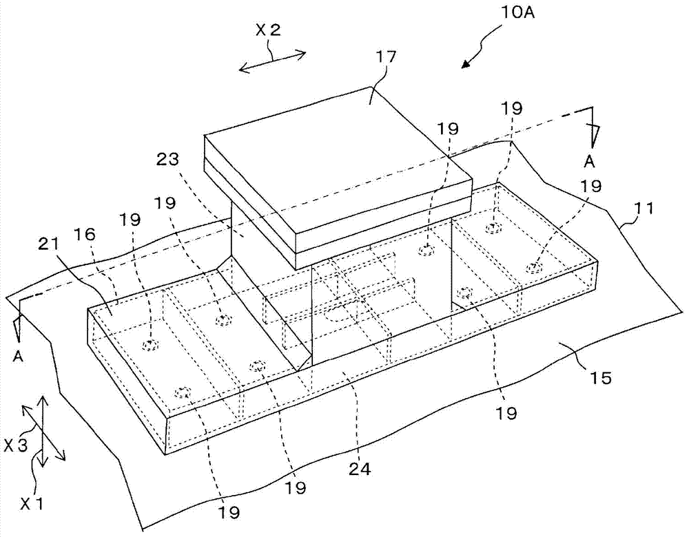
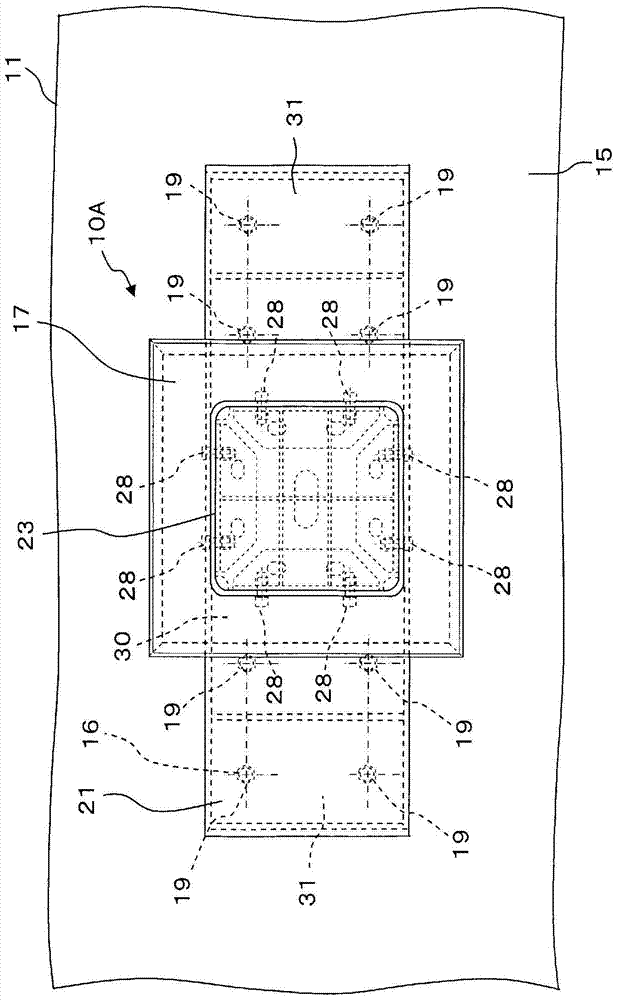
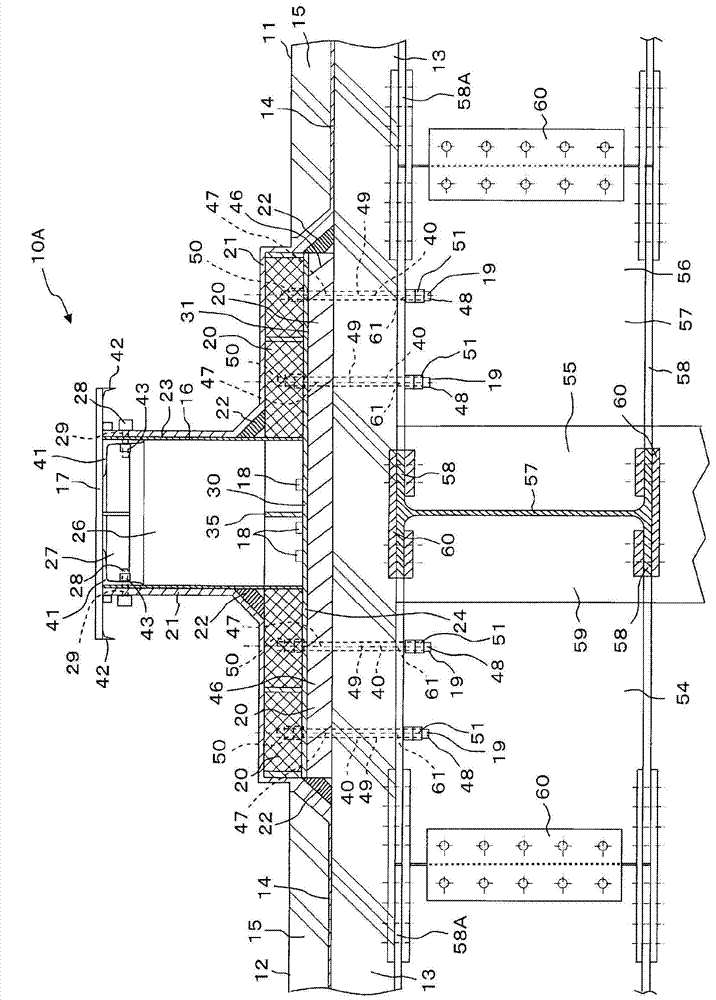
[0058] Referring to the perspective view of the mounting base 10A shown as an example figure 1 The installation base of the present invention is described in detail with accompanying drawings, content is as follows. exist figure 1 The figure shows one installation foundation 10A installed on the steel frame structure 11, but the number of foundations 10A is not limited to the number shown in the figure, generally speaking, two Above foundation 10A. in addition, figure 2 is a top view of the mounting base 10A, image 3 Yes figure 1 A-A sectional view of . Figure 4 is a top view of the metal base 16, Figure 5 is a side view of the metal base 16 . exist figure 1 Here, the up-down direction is indicated by an arrow X1, the lateral direction is indicated by an arrow X2, and the front-rear direction is indicated by an arrow X3.

[0059] The installation base 10A is installed at a predetermined installation position on the roof or underground of a steel frame structure 11...


PUM


Abstract

Problem: To provide a mounting base capable of decreasing the work and cost required for installation and capable of shortening construction time. Solution: A mounting base (10A) is formed from a metal foundation (16), height adjustment bolts (18) for adjusting the height dimension of the foundation (16), support bolts (19) inserted into support bolt insertion holes (39, 40), a metal cover (17) installed on the foundation (16), and mortar (20) filling the space (46) between the foundation (16) and the upper surface of a concrete slab (12). In the base (10A), the first fixed ends (47) of the bolts (19) are inserted into insertion holes (39) formed in a metal plate (24) and are fixed to the metal plate (24) with nuts (50), and the second fixed ends (48) of the bolts (19) are fixed to a steel beam (56) with nuts (51). The portion of the first fixed ends (47) of the bolts (19) which extends between the metal plate (24) and the top surface of the concrete floor (12) is integrated with the mortar (20) filling the space (46), and the metal cover (17) covers the opening (27) at the top of a metal tube (23) of the foundation (16).

Description

technical field [0001] The present invention relates to an installation foundation, and in more detail, relates to a construction for installing mechanical appliances such as solar panels, antennas, water storage tanks, purification tanks, air-conditioning equipment, iron towers, and steel-frame buildings on steel-frame structures. The above-mentioned steel frame structure has a steel frame body structure formed of steel frame columns and steel frame beams and a concrete slab (Japanese: コンクリート bed) arranged on the steel frame body structure. Background technique [0002] In concrete structures such as reinforced concrete structures and reinforced concrete structures of new buildings or old buildings, solar panels, antennas, water storage tanks, purification tanks, air-conditioning equipment, etc. are installed on the roof and underground slabs. Such mechanical appliances, iron towers, steel frame buildings and other buildings. Usually, for such machines and buildings, they ...

Claims


Application Information

Patent Timeline
Patent Type & Authority Applications(China)
IPC IPC(8): E04D13/00
CPCF24J2/5245E04B1/41E04B1/165F24F13/32F16M9/00E04D13/1407F24J2/525E04C5/00Y02E10/47F24S25/61F24S25/617E02D27/32
Inventor 高木一昌高木荣造
Owner MARUTAKA IND
Why Eureka
Try Eureka