
Spindle structure of winding machine

A technology of winding machine and main shaft, which is applied in the direction of conveying filamentous materials, thin material processing, transportation and packaging, etc. It can solve the problems of poor rotation accuracy of the main shaft and deformation of the shaft core of the main shaft, so as to improve the rotation accuracy and prolong the service life. Life, the effect of meeting the precision requirements of product processing

Active Publication Date: 2019-02-19
GUANGZHOU HAOZHI ELECTROMECHANICAL
View PDF6 Cites 0 Cited by
  • Summary
  • Abstract
  • Description
  • Claims
  • Application Information

AI Technical Summary

Problems solved by technology

With the development of the modern electrical processing industry, the requirements for the winding machine have also increased. Affect the processing precision of the winding machine; while the existing winding machine spindle, in the continuous processing process, the shaft core of the spindle is prone to deformation, and the rotation accuracy of the spindle is poor

Method used


Image

  • Spindle structure of winding machine

Examples


Embodiment Construction

[0016] Below, the present invention will be further described in conjunction with the accompanying drawings and specific implementation methods. It should be noted that, under the premise of not conflicting, the various embodiments described below or the technical features can be combined arbitrarily to form new embodiments. .

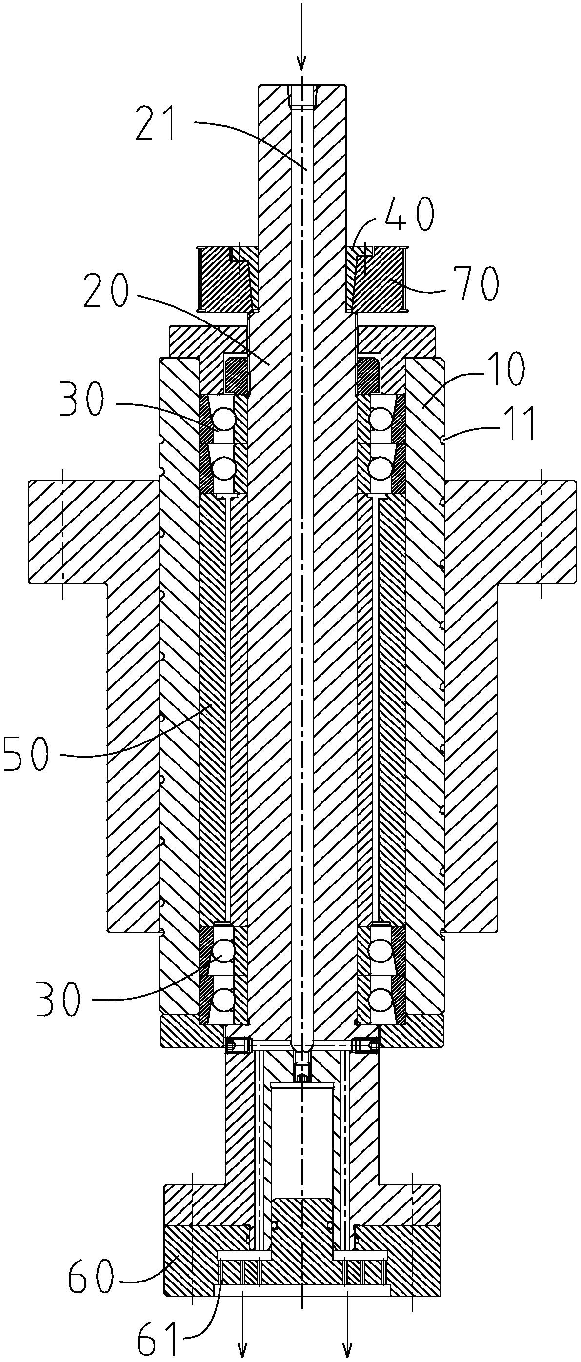
[0017] Such as figure 1 The main shaft structure of a winding machine shown includes a machine body 10, a shaft core 20, a winding mold base 60 and two sets of angular contact bearing assemblies 30; side, and respectively undertake the shaft core 20, at this time, the bearing has a higher rotation accuracy, which improves the rotation accuracy of the main shaft structure of the winding machine; the shaft core 20 is connected in the body 10, and a cooling channel 21 is provided; The wire mold is fixedly connected with the shaft core 20, and is provided with a cooling port 61 communicated with the cooling channel 21; thus, when the cooling gas is introd...


PUM


Abstract

The invention discloses a spindle structure of a winding machine. The spindle structure comprises a machine body, a spindle core, a bearing spacer sleeve, a winding mold seat and two groups of angularcontact bearing assemblies. The spindle core is connected in the machine body in a penetrating mode, provided with a cooling channel and fixedly connected with a winding mold provided with cooling openings communicating with the cooling channel. The two groups of angular contact bearing assemblies are arranged on the upper side and the lower side of the spindle core correspondingly and support the spindle core. The bearing spacer sleeve sleeves the spindle core and is positioned between two groups of angular contact bearing assemblies. Due to the adoption of the angular contact bearing assemblies and the cooperation of the cooling channel in the spindle core and the cooling openings in the winding mold seat, cooling gas passes through the cooling channel and the cooling ports, heat generated by the angular contact bearing assemblies can be taken away by the cooling gas, the rotating precision of the angular contact bearing assemblies is improved, and the spindle structure of the winding machine is high in rotating precision; and meanwhile, heat generated in the winding process can be taken away by the cooling gas, so that the cooling of the winding mold base is realized, and the possibility of deformation is reduced.

Description

technical field [0001] The invention relates to a main shaft structure, in particular to a main shaft structure of a winding machine. Background technique [0002] At present, the winding machine is a kind of coil winding processing for various motors, electromagnetic induction equipment, 3C electronic products and so on. With the development of the modern electrical processing industry, the requirements for the winding machine have also increased. It affects the processing precision of the winding machine; while the existing main shaft for winding machines, in the continuous processing process, the shaft core of the main shaft is prone to deformation, and the rotation accuracy of the main shaft is poor. Contents of the invention [0003] In order to overcome the deficiencies of the prior art, the purpose of the present invention is to provide a main shaft structure of a winding machine, which has better rotation accuracy and can reduce the possibility of deformation of t...

Claims


Application Information

Patent Timeline
Patent Type & Authority Applications(China)
IPC IPC(8): B65H54/44B65H54/74
CPCB65H54/44B65H54/74B65H2701/31
Inventor 黎训学汤秀清
Owner GUANGZHOU HAOZHI ELECTROMECHANICAL
Learn More