Single-diversion-tunnel water-power engineering hoist arrangement structure

A technology for water diversion tunnels and hydropower projects, which is applied in water conservancy projects, hydroelectric power generation, hydropower stations, etc. It can solve the problems of increasing investment, increasing the amount of excavation and concrete pouring, and achieves the effect of saving investment

Pending Publication Date: 2019-02-19
CHINA POWER CONSRTUCTION GRP GUIYANG SURVEY & DESIGN INST CO LTD
View PDF0 Cites 0 Cited by
  • Summary
  • Abstract
  • Description
  • Claims
  • Application Information

AI Technical Summary

Problems solved by technology

[0003] However, for single-diversion tunnel hydropower projects with two generators in one tunnel or three generators in one tunnel, because there is only one flow channel, the number of trash racks and layered water intake stacking beam doors is small, and there is only one maintenance gate and one fast gate. The two-way cleaning door crane and the two-way door crane of the existing technology are used to increase the investment more than the whole project; in addition, the layered water intake stacking gate and the maintenance gate are arranged at the end of the vertical water flow direction of the water inlet. The gate bank will greatly increase the amount of excavation and concrete pouring, especially for some water inlets that are difficult to excavate. Therefore, there are still deficiencies in the existing technology and need to be further improved

Method used


Image

  • Single-diversion-tunnel water-power engineering hoist arrangement structure
  • Single-diversion-tunnel water-power engineering hoist arrangement structure
  • Single-diversion-tunnel water-power engineering hoist arrangement structure

Examples


Embodiment

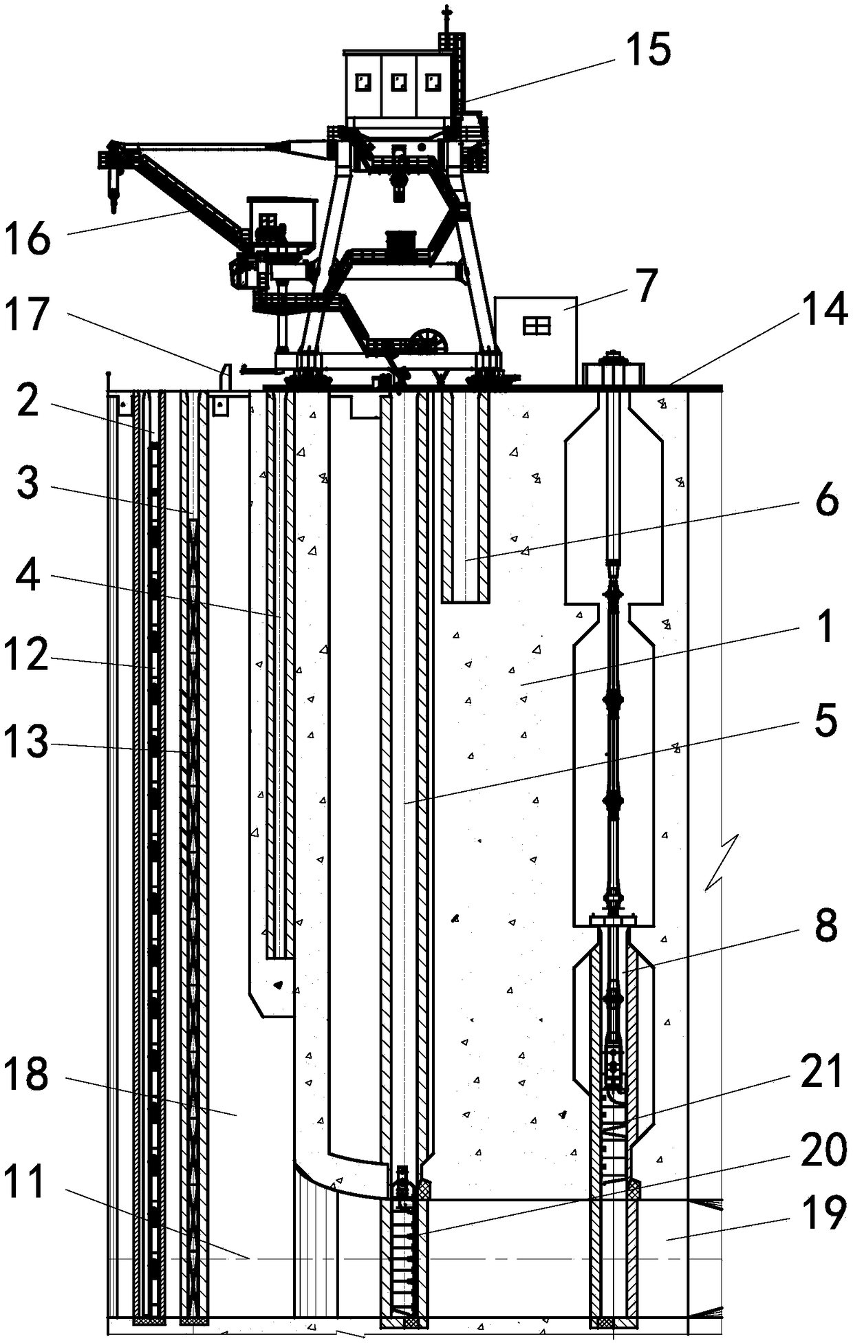
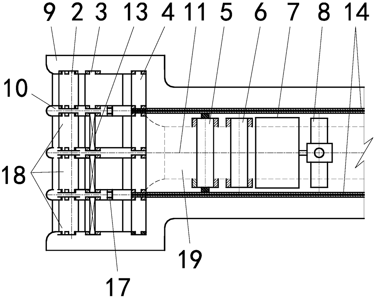
[0018] In this example, the trash rack slot 2, layered water intake stack beam door slot 3, layered water intake stack beam door storage 4, maintenance gate slot 5, maintenance gate storage 6, and hydraulic pump room 7 are sequentially arranged at the water inlet of the dam body 1 along the water flow direction And fast gate slot 8. The front section of the single diversion tunnel is divided into multiple flow channels 18 by two side piers 9 and more than one middle pier 10 ; the rear section of the single diversion tunnel is a single flow channel 19 .

[0019] Each flow channel of the multi-runner 18 is provided with a trash rack slot 2; a trash rack 12 is arranged in each trash rack slot 2; a layered water intake stack is arranged behind each trash rack slot 2 Beam door slot 3; each layered water intake stack door slot 3 is provided with a layered water intake stack door 13; each layered water intake stack door slot 3 is equipped with a layered water intake stack door storeh...


PUM


Abstract

The invention discloses a single-diversion-tunnel water-power engineering hoist arrangement structure. The single-diversion-tunnel water-power engineering hoist arrangement structure comprises a dam body (1) which is of a single diversion tunnel structure; the top surface of the dam body (1) is spread with two portal crane rails (14), and the two rails are symmetrical to the center line (11) of asingle diversion tunnel; the two ends of the portal crane rails (14) are provided with portal crane stop heads (17); the portal crane rails (14) are provided with a bidirectional portal crane (15) operating along the portal crane rails (14); and the upstream side of the bidirectional portal crane (15) is provided with two symmetrical rotation lifting devices (16). According to the single-diversion-tunnel water-power engineering hoist arrangement structure, operation of a trash holding fence, a layered water getting stop log gate and an bulkhead gate as well as installing and overhauling of a quick gate hydraulic hoist can be completed through only one bidirectional portal crane, one bidirectional trash removal portal crane can be saved, in addition, the end, perpendicular to the waterflowdirection, of the water inlet does not need to be provided with the layered water getting stop log gate and a gate chamber of the bulkhead gate so that the engineering investment can be reduced.

Description

technical field [0001] The invention relates to an arrangement structure of a hoist for a hydropower project of a single diversion tunnel, and belongs to the technical field of metal structures of a water conservancy and hydropower project. Background technique [0002] For hydropower projects, trash racks, layered water intake stack gates, maintenance gates and fast gates are usually arranged in sequence along the water inlet flow direction. Adopt two-way cleaning door machine operation, set one fast gate for each hole and use a single-cylinder vertical hydraulic hoist to operate, and set up a multi-hole shared inspection gate and use two-way door machine operation, consider storing stacked beams for layered water intake Gates and maintenance gates require layered water intake stacking gates and maintenance gates to be installed at the end of the vertical water flow of the water inlet. The existing technical scheme is reasonable for hydropower projects with more than two wa...

Claims


Application Information

Patent Timeline
IPC IPC(8): E02B9/06
CPCE02B9/06Y02E10/20
Inventor 王兴恩劳海军谭守林卢修迪
Owner CHINA POWER CONSRTUCTION GRP GUIYANG SURVEY & DESIGN INST CO LTD
Why Eureka
Try Eureka