A load adaptive variable voltage constant current source circuit

A variable voltage and constant current source technology, applied in the direction of adjusting electrical variables, instruments, control/regulation systems, etc., can solve problems such as poor load adaptability, rising internal power consumption of triodes, and triodes entering the undervoltage zone, etc.

Inactive Publication Date: 2020-10-20
JILIN UNIV
View PDF9 Cites 0 Cited by
  • Summary
  • Abstract
  • Description
  • Claims
  • Application Information

AI Technical Summary

Problems solved by technology

However, like other prior art constant current source circuits, this patent has the problem of poor load adaptability
Specifically, a constant current source circuit can only drive a fixed load, or only allow the load to change within a small range. When the load increases, the triode that controls the current will enter the saturation region, resulting in a rapid increase in the maximum output current. When the load decreases, the triode will enter the undervoltage region (because the load is small, the voltage generated at both ends of the load is also small, which is called undervoltage in this field. ), since the triode and the load are in the same series circuit, and the triode is a nonlinear device, the reduction of the load voltage will cause the triode to automatically bear the excess voltage of the circuit, which will lead to a sharp increase in the internal power consumption of the triode, while the internal power consumption of the triode It is a "by-product" of the circuit, which is harmful to the system: on the one hand, the increase in power consumption of the tube will increase the temperature of the tube sharply and increase the risk of tube burnout (reducing the service life of the instrument); on the other hand, when the load The inability to adjust the power supply in time during the change causes the efficiency of the entire circuit to be greatly reduced, which is very unfavorable when using a constant current source for mobile devices

Method used


Image

  • A load adaptive variable voltage constant current source circuit
  • A load adaptive variable voltage constant current source circuit
  • A load adaptive variable voltage constant current source circuit

Examples


Embodiment 1

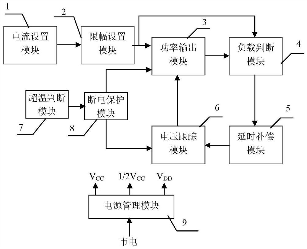
[0032] Embodiment 1 Overall structure of the present invention

[0033] Overall structure of the present invention is as figure 1 As shown, there are current setting module 1, limiting setting module 2, power output module 3, load judging module 4, delay compensation module 5, voltage tracking module 6, over-temperature judging module 7, power-off protection module 8 and power management Module 9; wherein, the current setting module 1 is connected to the limit setting module 2, and the limit setting module 2 is also connected to the power output module 3 and the load judgment module 4 respectively, and the power output module 3 is connected to the load judgment module 4, and the load judgment module 4 is connected to the delay compensation module 5, the delay compensation module 5 is connected to the voltage tracking module 6, the voltage tracking module 6 is connected to the power output module 3, the over-temperature judgment module 7 is connected to the power-off protection...

Embodiment 2

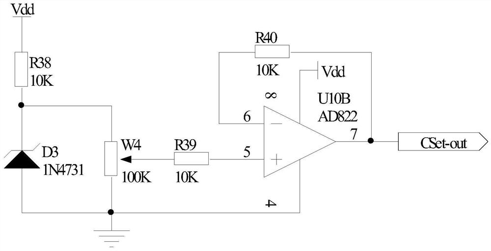
[0034] Embodiment 2 The current setting module of the present invention

[0035] The current setting module 1 of the present invention belongs to conventional technology, and can be conventionally designed according to actual needs, and can also adopt such as figure 2 In the structure shown, one end of the resistor R38 is connected to the power supply Vdd, the other end is connected to the cathode of the Zener diode D3 and a fixed end of the sliding rheostat W4, the anode of the Zener diode D3 is grounded, the other fixed end of the sliding rheostat W4 is grounded, and the resistor One end of R39 is connected to the sliding wire end of the sliding rheostat W4, the other end is connected to the non-inverting input end of the operational amplifier U10B, the inverting input end of the operational amplifier U10B is connected to one end of the resistor R38, and the other end of the resistor R38 is connected to the output end of the operational amplifier U10B. And as the output ter...

Embodiment 3

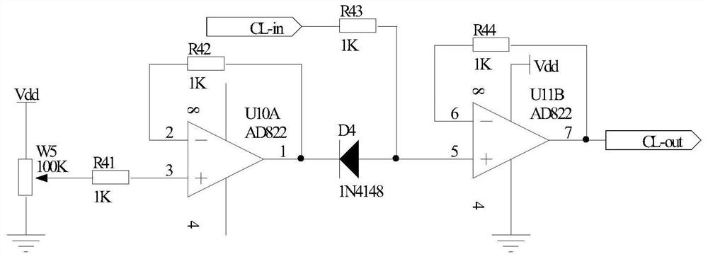
[0037] Embodiment 3 Limit setting module of the present invention

[0038] The principle circuit of limiter setting module 2 of the present invention is as image 3 As shown, one end of the resistor R43 is used as the input end of the limiter setting module 2, which is recorded as port CL-in, and the other end is connected to the non-inverting input end of the operational amplifier U11B and the positive pole of the diode D4, and the negative pole of the diode D4 is connected to the output of the operational amplifier U10A end and one end of the resistor R42, the other end of the resistor R42 is connected to the inverting input end of the operational amplifier U10A, the non-inverting input end of the operational amplifier U10A is connected to one end of the resistor R41, and the other end of the resistor R41 is connected to the sliding end of the sliding rheostat W5. One end of the rheostat W5 is connected to the power supply Vdd, the other end is grounded, the inverting input ...


PUM


Abstract

The invention provides a load self-adaptive variable voltage constant current source circuit, and belongs to the technical field of electronic equipment, the main structure comprises a current settingmodule (1), an amplitude limiting module (2), a power output module (3), a load judgment module (4), a delay compensation module (5), a voltage tracking module (6) and a power-off protection module (8). According to the load self-adaptive variable voltage constant current source circuit, load change can be actively adapted during the working process, the circuit has the advantages of high efficiency, wide load adapting range, high safety, high reliability and the like.

Description

technical field [0001] The invention belongs to the technical field of electronic equipment. It particularly relates to a load adaptive variable voltage constant current source circuit. Background technique [0002] Constant current sources have important applications in many fields such as LED drive, laser drive, sensor drive, and various glow discharge light source drives. The basic principle of the constant current source circuit is generally to use the nonlinear characteristics of the triode or FET and the deep negative feedback technology to make the output current controlled by the control voltage, and keep the current flowing through the load constant when the load changes. In the constant current source circuit, the stability of the current and the efficiency of the circuit are two crucial parameters. [0003] The existing technology closest to the present invention is the Chinese patent "A Double-loop Feedback Constant Current Source Circuit" (application number: ...

Claims


Application Information

Patent Timeline
Patent Type & Authority Patents(China)
IPC IPC(8): G05F1/567
CPCG05F1/567
Inventor 汝玉星于广安毕琳旭孙茂强杨忠岗
Owner JILIN UNIV
Why Eureka
Try Eureka