Rotary piston machine

A rotary piston and machine technology, applied in the field of rotary piston machines, can solve problems such as limited adaptability, achieve the effect of reducing leakage loss and improving efficiency

Inactive Publication Date: 2002-10-30
ROBERT BOSCH GMBH
View PDF2 Cites 0 Cited by
  • Summary
  • Abstract
  • Description
  • Claims
  • Application Information

AI Technical Summary

Problems solved by technology

As a result, the expansion ratio and compression ratio of the working chamber are limited, an...

Method used


Image

  • Rotary piston machine
  • Rotary piston machine
  • Rotary piston machine

Examples


Embodiment Construction

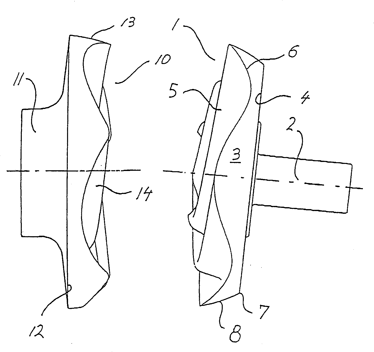
[0027] figure 1 The right side shows the power section 1 and the drive or output shaft 2 . A drive or output shaft 2, supported in a housing not shown in the figures, carries the power part 1 at one end thereof. The power part 1 is formed by a spherical section 3 which is bounded in the direction of the drive or output shaft 2 by a flat base 4 and whose end face 5 has helical cycloidal teeth. Different from the conventional cycloid structure, the cycloid 6 is formed by rolling a circle on the intersection line 7 between the spherical surface 8 and the bottom surface 4 , wherein the point of the circle describing the cycloid 6 is always on the spherical surface 8 . Cycloid 6 is the dominant curve required for gearing. A straight cycloidal tooth is produced when a straight generatrix moves along the dominant curve 6 around a fixed point on the axis of rotation of the drive or output shaft 2 . If instead of a straight generatrix a helical generatrix is ​​used, the helical cycl...


PUM


Abstract

The invention relates to a rotary piston machine, operating as a pump, compressor or motor, in which a cycloidal power part meshes with a correspondingly shaped closure part, wherein the difference in the number of teeth of the two parts is one. This results in working chambers ( 16 ) whose volumes reach a maximum and a minimum per revolution due to the synchronous rotation of the power part and the closing part.

Description

technical field [0001] The present invention relates to a rotary piston machine. Background technique [0002] A rotary piston machine is known (DE P 4241320.6; DE G 9218694.7; PCT / DE 92 / 01025), in which all the lines of the power part and the closing part forming the plane of rotation transverse to the direction of rotation, the extensions of which are through the intersection of the axes of rotation. As a result, the expansion ratio and compression ratio of the working chamber are limited, and the adaptability of the rotary prime mover to different working media and application ranges is limited. Contents of the invention [0003] The object of the present invention is to provide a rotary piston machine in which the suction and discharge characteristics of the working chambers are adjusted by means of a phase shift, so that undesired backflows or mixing of the sucked in with the working medium to be discharged is reduced. [0004] To achieve the above objects, the pres...

Claims


Application Information

Patent Timeline
IPC IPC(8): F01C3/08
CPCF01C3/08F01C3/085
Inventor 费里克斯·阿诺尔德
Owner ROBERT BOSCH GMBH
Why Eureka
Try Eureka