Stereo vision three-dimensional displacement measurement method based on synchronous sub-region search
A technology of stereo vision and displacement measurement, applied in the direction of measuring devices, image data processing, instruments, etc., can solve the problems of no synchronous sub-area search, low calculation efficiency in the measurement process, etc., and achieve the effect of improving calculation efficiency
- Summary
- Abstract
- Description
- Claims
- Application Information
AI Technical Summary
Problems solved by technology
Method used
Image
Examples
specific Embodiment approach 1
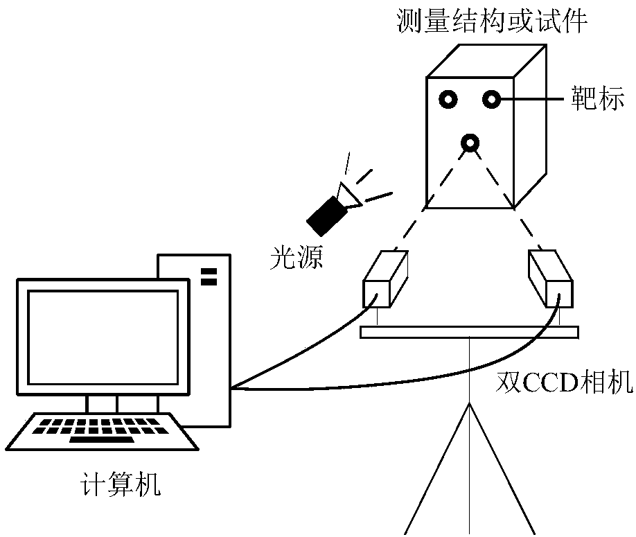
[0027] Specific implementation mode 1: The specific process of the stereo vision three-dimensional displacement measurement method based on synchronous sub-region search is as follows:
[0028] Step 1, adopt the camera calibration method to calibrate the stereo vision system, obtain the internal parameter matrix and the external parameter matrix of the stereo vision system, collect images for each measuring point, and obtain the left and right image sequences of each measuring point; the internal parameter matrix is the left camera The internal parameter matrix A of l and the internal parameter matrix A of the right camera r The left camera is the left camera of the stereo vision system, and the right camera is the right camera of the stereo vision system; the external parameter matrix is the rotation matrix R and the translation vector T from the left camera coordinate system to the right camera coordinate system; The measuring point is the center of the circular target ...
specific Embodiment approach 2
[0034] Specific embodiment 2: The difference between this embodiment and specific embodiment 1 is that in the step 1, the camera calibration method is used to calibrate the stereo vision system, and the internal parameter matrix and the external parameter matrix of the stereo vision system are obtained. Collect images to obtain the left and right image sequences of each measuring point; the internal parameter matrix is the internal parameter matrix A of the left camera l and the internal parameter matrix A of the right camera r The left camera is the left camera of the three-dimensional displacement measurement system, and the right camera is the right camera of the three-dimensional displacement measurement system; the external parameter matrix is a rotation matrix R and a translation vector T from the left camera to the right camera coordinate system; The specific process of measuring the point as the center of the circular target is as follows:
[0035] In the whole pr...
specific Embodiment approach 3
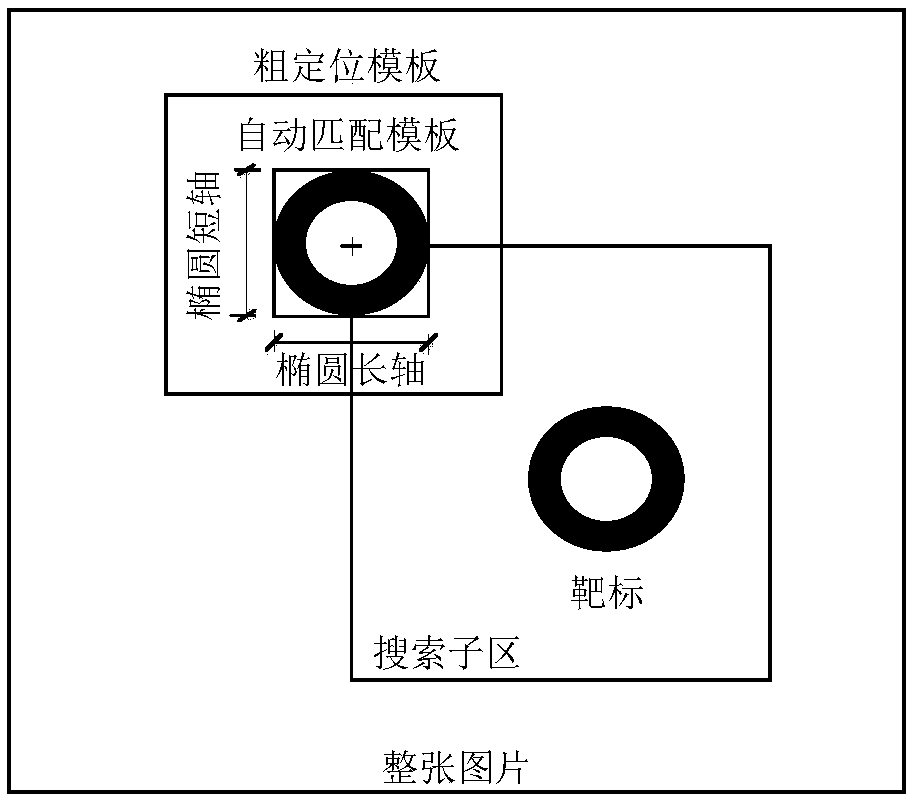
[0039]Specific embodiment three: the difference between this embodiment and specific embodiment one or two is that: in the step two, the image coordinates of each measuring point on the left image at the initial moment are extracted, the DIC matching template of each measuring point is automatically generated, and each measuring point is calculated. The DIC search sub-region size of measuring point; Described left image is the image that left camera collects; Described DIC method is that the concrete process of digital image correlation method is:
[0040] Step 21, roughly locate the DIC matching template area of each measuring point on the left image:
[0041] On the left camera image at the initial moment, the SUSAN filtering method is first used to filter and denoise the image. The beneficial effect is to better maintain the original structure and characteristics of the image, and at the same time sharpen the boundaries and corners of the image to improve the image quality...
PUM
 Abstract
Description
Claims
Application Information
 - R&D
- Intellectual Property
- Life Sciences
- Materials
- Tech Scout
- Unparalleled Data Quality
- Higher Quality Content
- 60% Fewer Hallucinations
Browse by: Latest US Patents, China's latest patents, Technical Efficacy Thesaurus, Application Domain, Technology Topic, Popular Technical Reports.
© 2025 PatSnap. All rights reserved.Legal|Privacy policy|Modern Slavery Act Transparency Statement|Sitemap|About US| Contact US: help@patsnap.com


