Preserved duck egg mud cleaning machine
A technology of preserved egg and cleaning machine, which is applied in the direction of cleaning devices, conveyors, conveyor objects, etc., which can solve the problems of inconvenient cleaning, sticky mud, complicated operation, etc., and achieve the effect of easy cleaning
- Summary
- Abstract
- Description
- Claims
- Application Information
AI Technical Summary
Problems solved by technology
Method used
Image
Examples
Embodiment 1
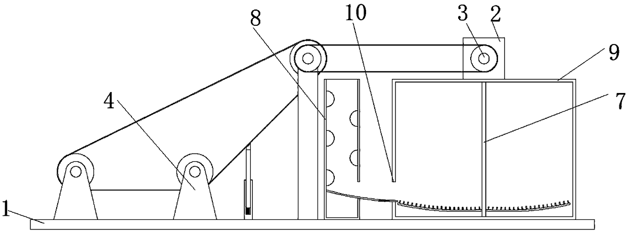
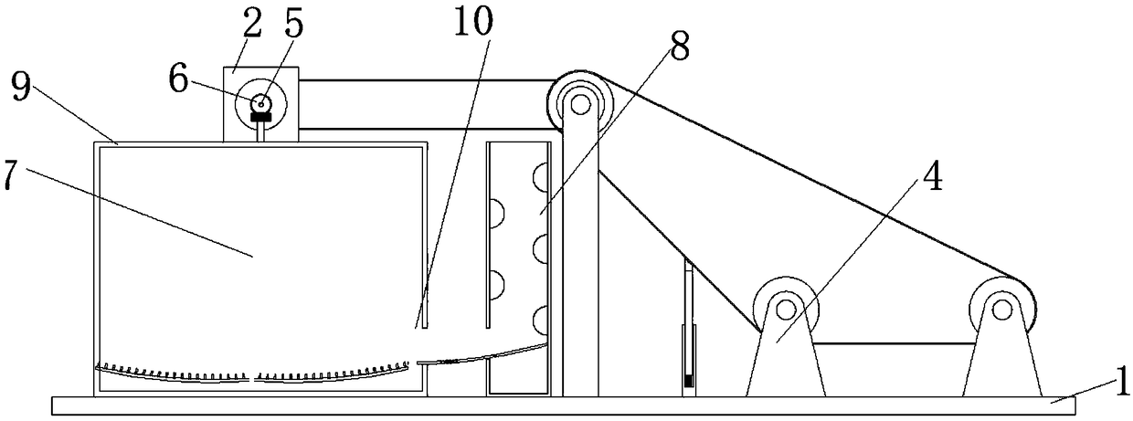
[0047] Such as Figure 1-2 As shown, the present invention provides a kind of technical scheme: a kind of preserved egg mud cleaning machine, comprises working board 1, and the top of working board 1 is fixedly connected with organism A9, and the top of body A9 is fixedly connected with biaxial motor 2, biaxial motor 2 is a YZR2 series double-axis motor, the front of the double-axis motor 2 is fixedly connected with a rotating shaft A3 through a flat key, the surface of the rotating shaft A3 is provided with a preserved egg feeding mechanism 4, and the bottom of the preserved egg feeding mechanism 4 is connected to the working plate 1 Connection, the output end on the back of the double-axis motor 2 is fixedly connected with the rotating shaft B5 through a flat key, and the surface of the rotating shaft B5 is fixedly connected with a bevel gear A6, and the bottom of the bevel gear A6 is provided with a mud wiping mechanism 7, through The mutual cooperative operation of the mat...
Embodiment 2
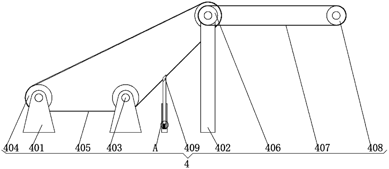
[0049] Such as Figure 1-5 As shown, on the basis of Embodiment 1, the present invention provides a kind of technical scheme: preserved egg feeding mechanism 4 includes two U-shaped plates A401 and a U-shaped plate B402 fixedly connected with the body A9, and the U-shaped plate A401 A rotating shaft C403 is movably connected to both sides of the inner wall of the U-shaped plate B402. The rotating shaft C403 forms a triangle, and the included angle ∠α is 120-135°. By setting ∠α as an included angle of 120-135° , making it more stable during transportation, the surface of the rotating shaft C403 is fixedly connected with a runner A404, and the three runners A404 are connected with a conveyor belt 405, and the runner A404 on the right side of the U-shaped plate A401 is located on the right At the bottom, the front of one of the rotating shafts C403 runs through the U-shaped plate B402 and is fixedly connected to the rotating wheel B406. The right side of the rotating wheel B406 i...
Embodiment 3
[0051] Such as Figure 1-7 As shown, on the basis of Embodiment 1 and Embodiment 2, the present invention provides a technical solution: the mud wiping mechanism 7 includes a bevel gear B701 meshing with the bevel gear A6, and the bottom of the bevel gear B701 is fixedly connected with The rotating shaft D702, the bottom of the rotating shaft D702 penetrates the inside of the body 1, eight sets of chute 703 are provided on the surface of the rotating shaft D702, and a sliding bar 704 is fixedly connected between the top and the bottom of the inner wall of the chute 703, and the sliding bar 704 Slide block 705 is movably connected on the surface, and the buffer spring 706 that is positioned at slide bar 704 outside is fixedly connected between the bottom of slide block 705 and the inwall of chute 703, by setting chute 703, slide bar 704, slide block 705, buffer The spring 706, in the process of centrifugal rotation, utilizes the elastic force of the buffer spring 706 to make th...
PUM
 Abstract
Description
Claims
Application Information
 - R&D
- Intellectual Property
- Life Sciences
- Materials
- Tech Scout
- Unparalleled Data Quality
- Higher Quality Content
- 60% Fewer Hallucinations
Browse by: Latest US Patents, China's latest patents, Technical Efficacy Thesaurus, Application Domain, Technology Topic, Popular Technical Reports.
© 2025 PatSnap. All rights reserved.Legal|Privacy policy|Modern Slavery Act Transparency Statement|Sitemap|About US| Contact US: help@patsnap.com


