Cutting blade and cutting tool for inner hole processing

A technology of cutting blades and cutting tools, which is applied in the direction of cutting tools, cutting blades, and manufacturing tools for lathes, can solve the problems of reducing the strength of cutting blades and tool holders, affecting processing efficiency and processing stability, etc., and achieves compact structure, Stable positioning and simple installation

Active Publication Date: 2019-02-22
ZHUZHOU CEMENTED CARBIDE CUTTING TOOLS CO LTD
View PDF9 Cites 3 Cited by
  • Summary
  • Abstract
  • Description
  • Claims
  • Application Information

AI Technical Summary

Problems solved by technology

However, the cross-sectional size of this type of cutting blade and tool holder is very small, and the screw countersunk hole and threaded hole greatly reduce the strength of the cutting blade and cutter holder, which seriously affects the processing efficiency and processing stability.

Method used


Image

  • Cutting blade and cutting tool for inner hole processing
  • Cutting blade and cutting tool for inner hole processing
  • Cutting blade and cutting tool for inner hole processing

Examples


Embodiment Construction

[0044] The present invention will be further described in detail below in conjunction with the accompanying drawings and specific embodiments.

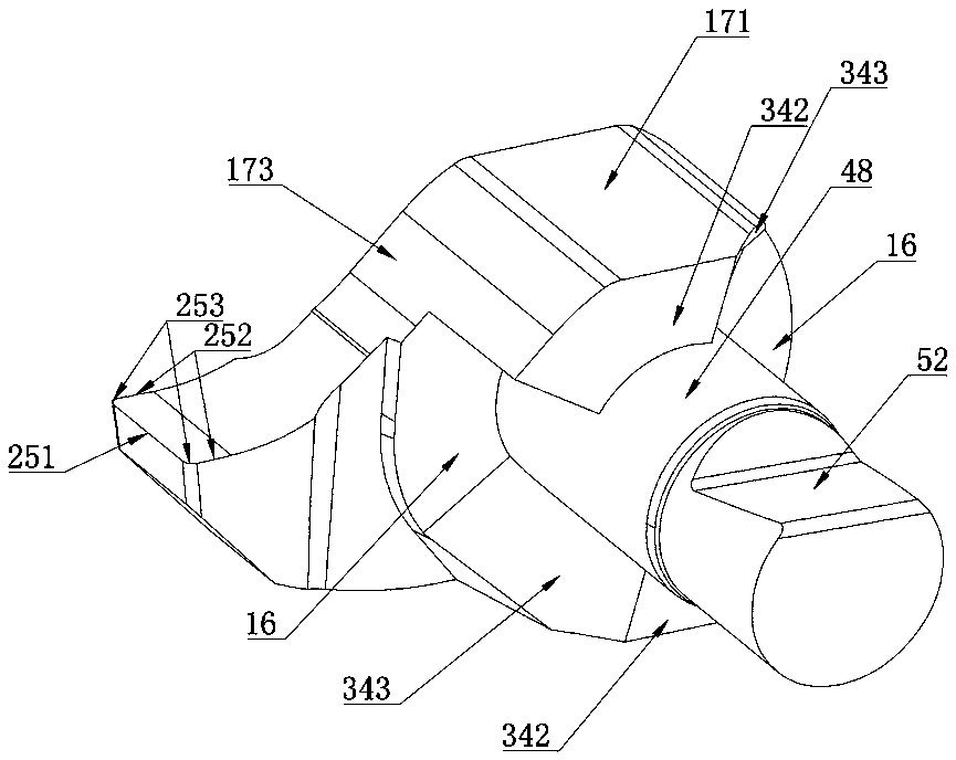
[0045] Such as Figures 1 to 5 As shown, the cutting insert for inner hole processing in this embodiment includes a front surface 15, a rear surface 16, a main side 17 vertically connected between the front surface 15 and the rear surface 16, a cutting portion 25 and a mounting portion 30, The cutting part 25 is located on the main side 17, and the mounting part 30 is located on the middle part of the rear surface 16. The rear surface 16 is provided with more than two bosses 34, and the bosses 34 are arranged symmetrically along the circumferential direction of the mounting part 30. A locking surface 521 is provided on the outer peripheral wall on one side of the surface 16 .

[0046] In the cutting blade of the present invention, the rear surface 16 is provided with more than two bosses 34, and the mounting part 30 is provided with ...


PUM


Abstract

The invention discloses a cutting blade for inner hole processing. The cutting blade for inner hole processing comprises a front surface, a back surface, a main side surface perpendicularly connectedbetween the front surface and the back surface, a cutting part and an installation part, wherein the cutting part is located on the main side surface; the installation part is located in the middle ofthe back surface; more than two bosses are arranged on the back surface and are arranged along the circumferential direction of the installation part; and a locking surface is arranged on the peripheral wall of one side, far away from the back surface, of the installation part. The invention further provides a cutting tool which comprises a cutter bar, a fastening screw and the blade, wherein theblade is the cutting blade; a positioning groove for holding the blade is formed in the front end of the cutter bar; and a threaded hole for installing the fastening screw is formed in the peripheralsurface of the front end of the cutter bar. The cutting blade and cutting tool for inner hole processing provided by the invention has the advantages of high strength and accuracy in positioning.

Description

technical field [0001] The invention relates to the technical field of metal cutting, in particular to a cutting insert and a cutting tool for inner hole processing. Background technique [0002] In small diameter bore (D min ≥6mm) in the field of processing, there are many kinds of connection mechanisms for detachably fastening the cutting blade on the tool holder, most of which design a screw countersunk hole at the center of the end face of the cutting blade, and lock and fix the blade from the end face with the screw On the tool holder (such as patent CN103347630A, US patent US20110200408, German patent DE29807797U1, etc.). However, the cross-sectional size of this type of cutting blade and tool holder is very small, and the screw countersunk holes and threaded holes greatly reduce the strength of the cutting blade and cutter holder, seriously affecting the processing efficiency and processing stability. Contents of the invention [0003] The technical problem to be ...

Claims


Application Information

Patent Timeline
Patent Type & Authority Applications(China)
IPC IPC(8): B23B27/16
CPCB23B27/1622B23B2200/12B23B2200/161B23B2200/28
Inventor 宁华林王东海张京刘孙和
Owner ZHUZHOU CEMENTED CARBIDE CUTTING TOOLS CO LTD
Why Eureka
Try Eureka