Axial-position-adjustable discharging shaft of die-cutting machine

An axial position and adjustable technology, applied in metal processing and other directions, can solve the problems of undiscovered patent documents, inability to achieve axial position adjustment, and easy wear of the fixed position, so as to improve the easy wear problem, facilitate installation, Tension stabilization effect

Pending Publication Date: 2019-02-22
中融飞腾(北京)科技有限公司
View PDF6 Cites 2 Cited by
  • Summary
  • Abstract
  • Description
  • Claims
  • Application Information

AI Technical Summary

Problems solved by technology

[0003] The structure and function of the existing discharge shaft are relatively single, and the adjustment of the axial position and direction cannot be realized, and the application is unstable and inconvenient. The material has the phenomenon of self-rotation and sliding, which destroys the set tension, resulting in large changes in product size, excessive Poor quality, lower product yield, lower production efficiency, etc.
In addition, the positioning of the existing die-cutting materials is realized by nylon retaining rings, but the retaining rings of this material are easy to wear after a period of application, which will bring product quality risks during the production process
[0004] Through searching, no published patent documents identical or similar to the patent of the present invention have been found

Method used


Image

  • Axial-position-adjustable discharging shaft of die-cutting machine
  • Axial-position-adjustable discharging shaft of die-cutting machine
  • Axial-position-adjustable discharging shaft of die-cutting machine

Examples


Embodiment Construction

[0021] The present invention will be further described in detail below through the specific examples, the following examples are only descriptive, not restrictive, and cannot limit the protection scope of the present invention with this.

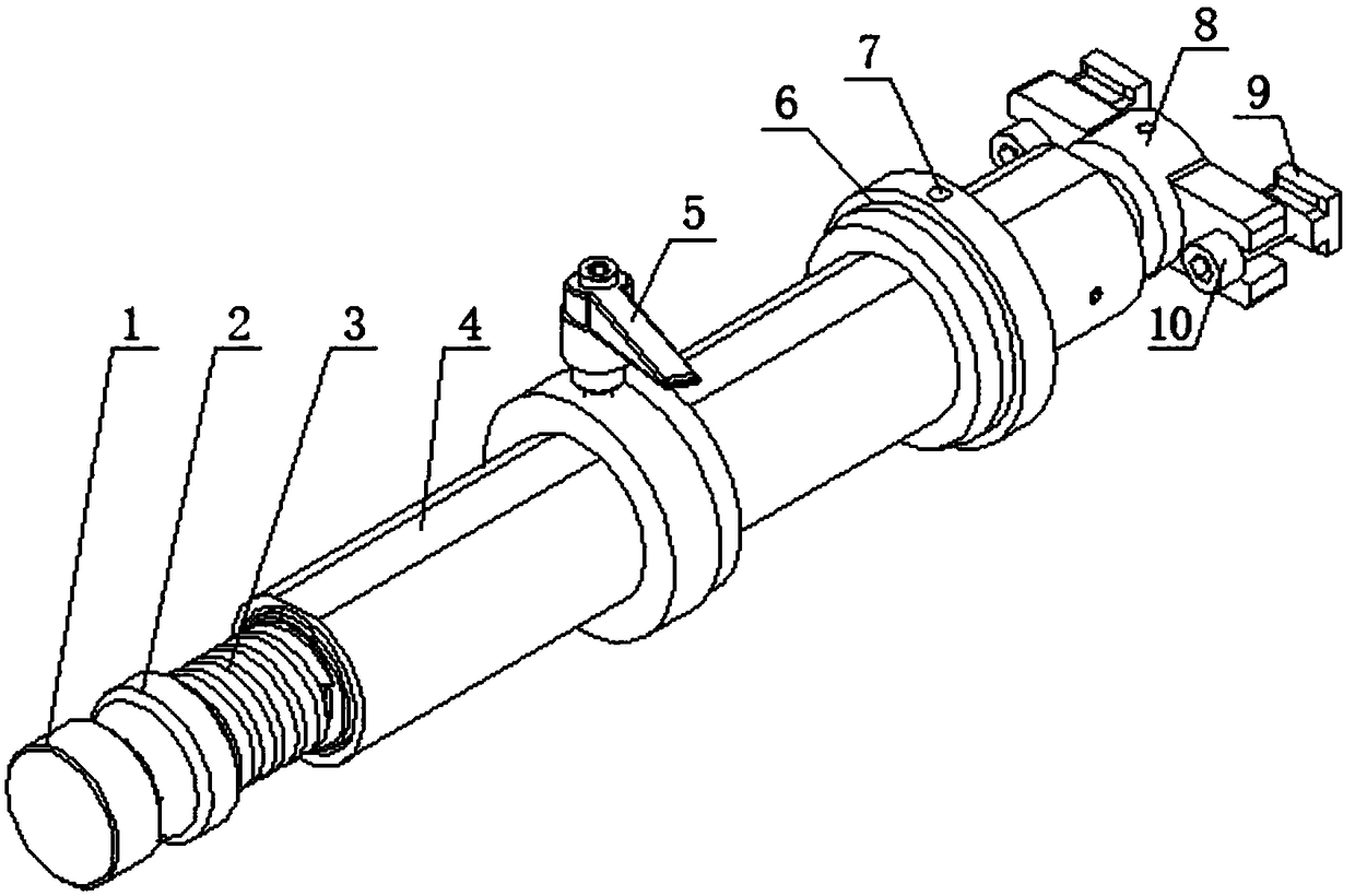
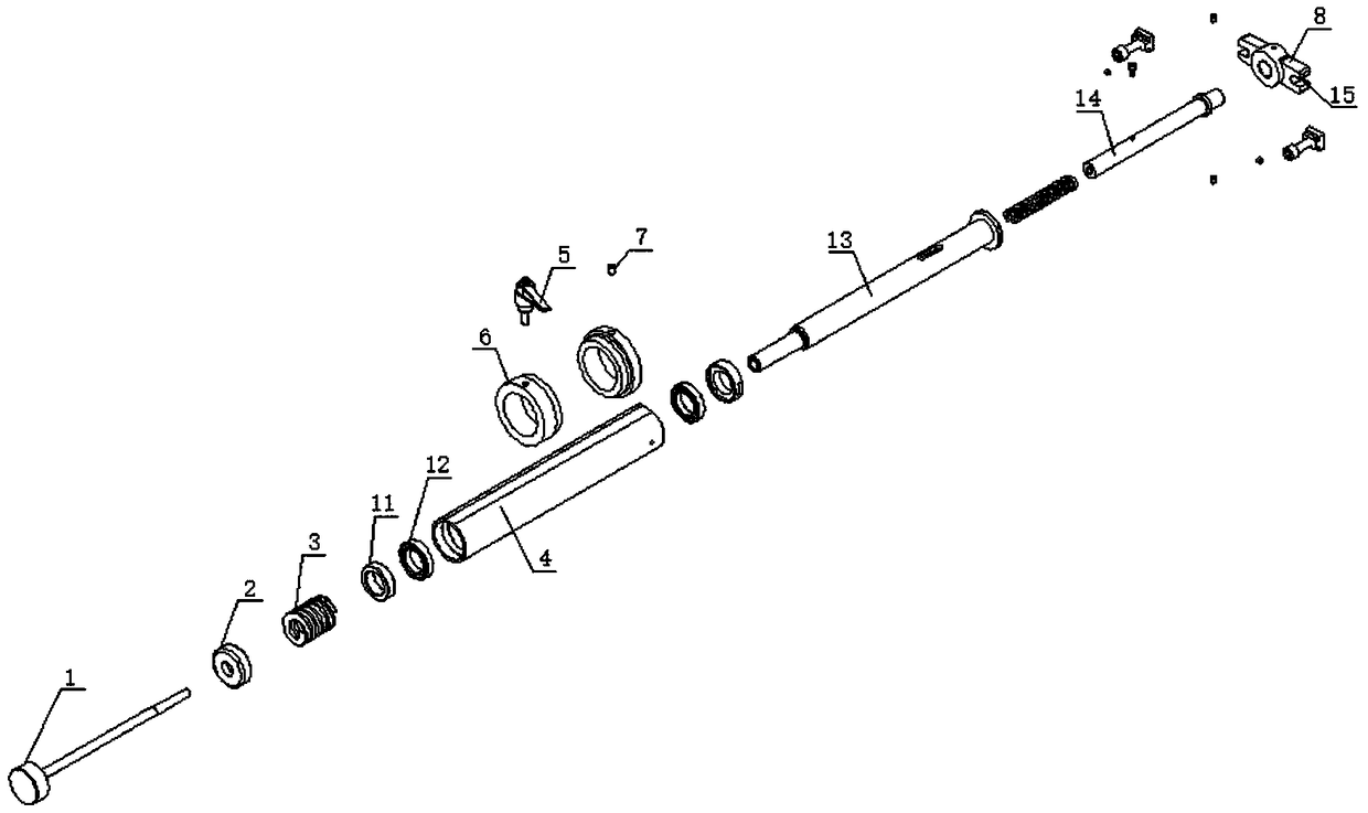
[0022] A die-cutting machine discharge shaft whose axial position can be adjusted is characterized in that it consists of a shaft casing 4, a bearing 12, a spring 3, an adjusting nut 2, an adjusting screw 1, a spring casing 13, a base mandrel 14, and a mounting base 8. The aluminum retaining ring 6 is composed of an adjusting nut, a spring, a washer 11 and a bearing on the left end of the shaft casing through the adjusting screw from left to right, and the spring casing is passed through the spring casing at the right end of the shaft casing. Bearings and washers are installed sequentially from left to right. Bosses are provided at both ends of the shaft casing, and the bearings are embedded in the bosses. The adjusting screw and the spring c...


PUM


Abstract

The invention relates to an axial-position-adjustable discharging shaft of a die-cutting machine. The discharging shaft is characterized by being composed of a shaft body housing, a bearing, a spring,an adjusting nut, an adjusting screw, a spring housing, a base mandrel, a mounting base and an aluminum retaining ring, wherein the left end of the shaft body housing sequentially passes through theadjusting nut, the spring, a gasket and the bearing through the adjusting screw from left to right; the right end of the shaft body housing passes through the bearing and the gasket through the springhousing from left to right; the adjusting screw and the spring housing are in threaded connection in the shaft body housing; the spring and the base mandrel are sequentially arranged in the right endof the spring housing from inside to outside; the mounting base is mounted at the right end of the base mandrel; and the aluminum retaining ring sleeves the shaft body housing. The axial-position-adjustable discharging shaft is scientific and reasonable in structural design and has the advantages of being stable in tension, long in service life, adjustable in axial position and convenient to position, guaranteeing die cutting quality and being easy to implement.

Description

technical field [0001] The invention belongs to the field of die-cutting accessories, and relates to a discharge shaft, in particular to a discharge shaft of a die-cutting machine whose axial position can be adjusted. Background technique [0002] Die-cutting machines are mainly used in the manufacturing fields of mobile phones, digital cameras, handheld computers, LCDs, automobiles, packaging, etc. The important components on the die-cutting shaft are mainly used for self-adhesive, EVA, double-sided adhesive, electronics, and mobile phone rubber pads. , 3M glue, dust-proof materials, heat-resistant insulation materials, shock-proof products, adhesive products, backlight and other auxiliary die-cutting products. [0003] The structure and function of the existing discharge shaft are relatively single, and the adjustment in the axial direction cannot be realized, and the application is unstable and inconvenient. The material has the phenomenon of self-rotation and sliding, wh...

Claims


Application Information

Patent Timeline
Patent Type & Authority Applications(China)
IPC IPC(8): B26F1/38B65H75/24
CPCB65H75/241B26F1/38
Inventor 肖建阳蔡玉星苏强胡延峰周立国董红雨张立红
Owner 中融飞腾(北京)科技有限公司
Why Eureka
Try Eureka