
Automobile charging pile capable of preventing from being blown down by wind

A car charging and sliding rod technology, which is applied to electric car charging technology, charging stations, electric cars, etc., can solve the problems of being easily blown down by strong winds and damage to car charging piles, and achieves fast and convenient height adjustment and prevents it from being blown by the wind Inverted, the effect of simple structure

Inactive Publication Date: 2019-02-22
安顺云首创科技开发有限公司
View PDF5 Cites 4 Cited by
  • Summary
  • Abstract
  • Description
  • Claims
  • Application Information

AI Technical Summary

Problems solved by technology

[0002] The function of the charging pile is similar to the refueling machine in the gas station. It can be fixed on the ground or wall, and installed in public buildings (public buildings, shopping malls, public parking lots, etc.) and residential area parking lots or charging stations. For charging various types of electric vehicles, the input end of the charging pile is directly connected to the AC power grid, and the output end is equipped with a charging plug for charging the electric vehicle. The charging pile generally provides two charging methods: conventional charging and fast charging. People can Use a specific charging card to swipe the card on the human-computer interaction interface provided by the charging pile to perform operations such as charging method, charging time, and cost data printing. The display screen of the charging pile can display data such as charging amount, cost, and charging time. In the prior art, because the car charging pile is erected on the side of the road, it is easy to be blown down by the strong wind, and it is easy to cause damage to the car charging pile, so it cannot meet people's needs

Method used


Image

  • Automobile charging pile capable of preventing from being blown down by wind
  • Automobile charging pile capable of preventing from being blown down by wind
  • Automobile charging pile capable of preventing from being blown down by wind

Examples


Embodiment Construction

[0023] The following will clearly and completely describe the technical solutions in the embodiments of the present invention with reference to the accompanying drawings in the embodiments of the present invention. Obviously, the described embodiments are only some, not all, embodiments of the present invention.

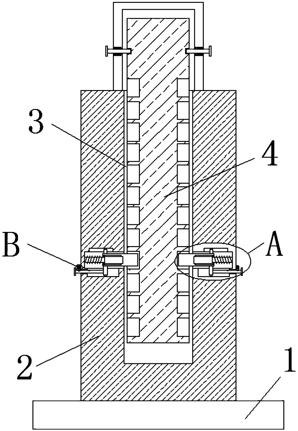
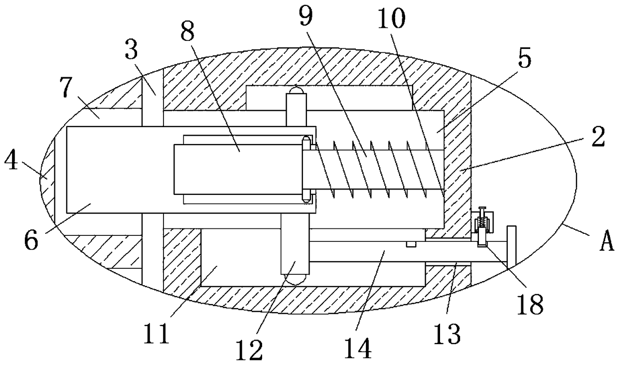
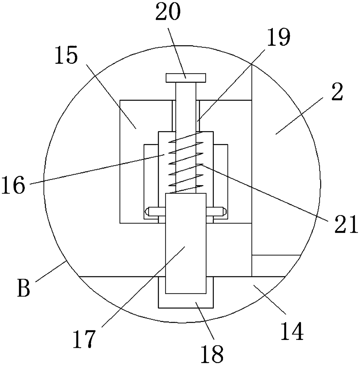
[0024] refer to Figure 1-3 , a wind-resistant car charging pile, including a mounting base 1, a fixing column 2 is fixedly installed on the top of the mounting base 1, a placement groove 3 is opened on the top of the fixing column 2, and a car charging pile body is placed in the placement groove 3 4, and the top of the car charging pile body 4 extends to the top of the mounting seat 1, and the inner walls of both sides of the placement groove 3 are provided with a first groove 5, and a first sliding rod 6 is slidably installed in the first groove 5, Both sides of the car charging pile body 4 are provided with first card slots 7, and the ends of the two first sliding...


PUM


Abstract

The invention discloses an automobile charging pile capable of preventing from being blown down by wind. The automobile charging pile comprises a mounting base; the top part of the mounting base is fixedly provided with a fixed column; a holding slot is formed in the top part of the fixed column; an automobile charging pile body is arranged in the holding slot; the top end of the automobile charging pile body extends to a position above the mounting base; a first groove is formed in the inner wall of each of the two sides of the holding slot; a first sliding rod is glidingly arranged in each first groove; a first clamping slot is formed in each of the two sides of the automobile charging pile body; and mutually adjacent ends of the two first sliding rods are correspondingly installed in the first clamping slots in manner of clamping. The automobile charging pile disclosed by the invention is simple in structure and convenient to operate; the automobile charging pile body can be rapidlyand conveniently adjusted in height, and thus, the automobile charging pile body can favorably stretch out and draw back in face of big wind, so that the stress surface of the automobile charging pile body is reduced, the automobile charging pile body is prevented from being blown down by wind, losses of people are reduced, and needs of people are satisfied.

Description

technical field [0001] The invention relates to the technical field of automobile charging piles, in particular to an automobile charging pile resistant to being blown down by wind. Background technique [0002] The function of the charging pile is similar to the refueling machine in the gas station. It can be fixed on the ground or wall, and installed in public buildings (public buildings, shopping malls, public parking lots, etc.) and residential area parking lots or charging stations. For charging various types of electric vehicles, the input end of the charging pile is directly connected to the AC power grid, and the output end is equipped with a charging plug for charging the electric vehicle. The charging pile generally provides two charging methods: conventional charging and fast charging. People can Use a specific charging card to swipe the card on the human-computer interaction interface provided by the charging pile to perform operations such as charging method, ch...

Claims


Application Information

Patent Timeline
Patent Type & Authority Applications(China)
IPC IPC(8): B60L53/31B60L53/30
CPCY02T10/70Y02T10/7072Y02T90/12
Inventor 于晓刚肖汉明
Owner 安顺云首创科技开发有限公司
Learn More