Guide mechanism of conveying chain

A conveyor chain and guide rod technology, applied in conveyors, transportation, packaging, packaging, etc., can solve the problems of large noise pollution, expensive conveyor chains, etc., to reduce maintenance and use costs, eliminate noise pollution, and extend service life The effect of longevity

Inactive Publication Date: 2019-02-22
徐州三石工控科技有限公司
View PDF0 Cites 2 Cited by
  • Summary
  • Abstract
  • Description
  • Claims
  • Application Information

AI Technical Summary

Problems solved by technology

This process also produces a lot of noise pollution
And a set of conveyor chains is often quite expensive

Method used


Image

  • Guide mechanism of conveying chain

Examples


Embodiment Construction

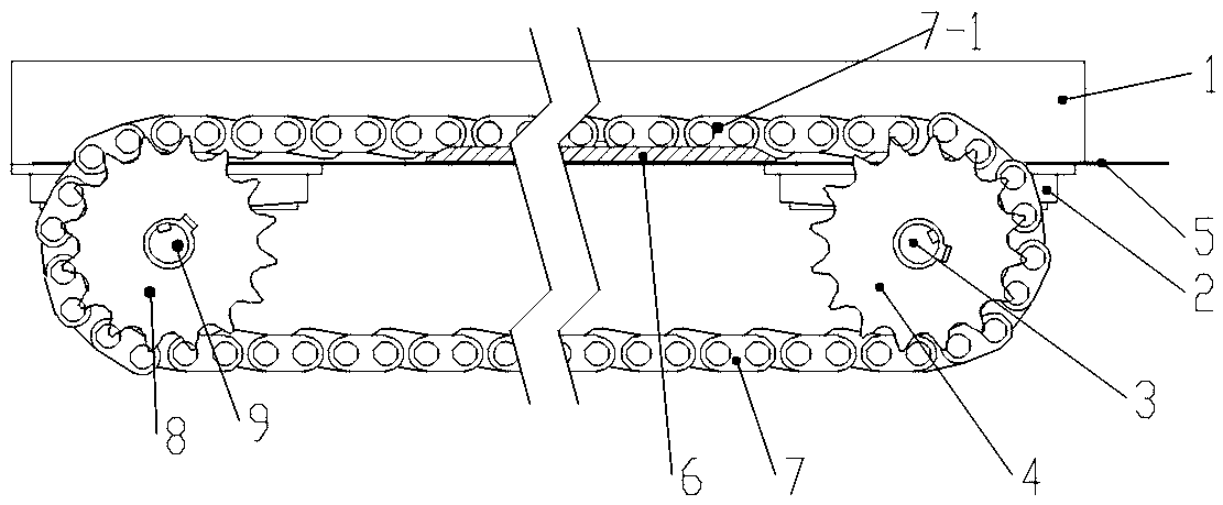
[0013] Such as figure 1 As shown, a guiding mechanism of a conveyor chain includes a conveyor sprocket, a conveyor chain, a lifting pallet and a guide rod; the conveyor chain is divided into a driving sprocket 4 and a driven sprocket 8, and the driving sprocket 4 and the drive shaft 3-key connection, the drive shaft 3 is supported on the mounting bracket 1 by the bearing assembly 2, and connected to the driving device; the driven sprocket 8 is key-connected to the rotating shaft 9 installed on the bearing assembly 2, and the conveyor chain 7 is linked to the drive sprocket 4 and the driven sprocket 8, so that the driving sprocket 4 can drive the driven sprocket 8 to rotate; the lifting pallet 5 is also installed on the mounting bracket 1, and the lifting pallet 5 is connected to the mounting bracket 1 or the bearing assembly 2 through bolts Connected, located below the uplink chain 7-1; a guide rod 6 is fixedly connected to the lifting pallet 5, the guide rod 6 is cylindrical,...


PUM


Abstract

The invention relates to a guide mechanism of a conveying chain. The guide mechanism of the conveying chain comprises conveying chain wheels and the conveying chain connected with the conveying chainwheels in a meshed manner. The conveying chain wheels are rotationally connected with bearing assemblies installed on an equipment support. A lifting support plate is arranged below an upstream chainbody of the conveying chain. A guide rod is fixedly connected with the lifting support plate. The two ends of the guide rod are arranged to be bevel angles, and the inclined faces are upward. The guide rod is parallel to the upstream chain body. When the conveying chain operates, conveying chain rollers slide on the guide rod horizontally. According to the guide mechanism of the conveying chain, the guide rod is a guide device, the chain is connected with the guide rod in a tensioned manner, and therefore a conveying chain system is in the low-wear, low-noise and stable-operation state; due tothe bevel angles at the two ends of the guide rod, the impact force existing when a rod body makes contact with the conveying chain is eliminated; and in this way, the service life of the conveying chain is prolonged, noise pollution is eliminated, and the maintenance and use cost is lowered.

Description

technical field [0001] The invention relates to the field of chain transmission, in particular to a guiding mechanism for a transmission chain. Background technique [0002] With the gradual and in-depth development of agricultural mechanization, various agricultural machinery with conveyor chain mechanisms emerge in endlessly, and a considerable part of the damage is caused by the wear and vibration of the chain and chain plates. This process also produces a lot of noise pollution. And a set of conveyor chains is often quite expensive. The purpose of the present invention is to remedy the existing technical problems and provide a simple, stable, durable and economical structure. Contents of the invention [0003] The object of the present invention is to remedy the existing technical problems and provide a simple, stable, durable, and economical conveyor chain guiding mechanism structure. [0004] The technical solution adopted by the present invention is: a guiding me...

Claims


Application Information

Patent Timeline
Patent Type & Authority Applications(China)
IPC IPC(8): B65G21/20
CPCB65G21/2063B65G2207/32
Inventor 王成文张洁钟志堂崔军吴晓伟王成力
Owner 徐州三石工控科技有限公司
Why Eureka
Try Eureka