
Feeding device for PCBs

A technology of PCB board and board support, which is applied in the field of PCB board feeding device, and can solve the problems of cumbersome and time-wasting PCB board transfer and feeding procedures

Inactive Publication Date: 2019-02-22
ANHUI SHENZE ELECTRONICS TECH
View PDF8 Cites 9 Cited by
  • Summary
  • Abstract
  • Description
  • Claims
  • Application Information

AI Technical Summary

Problems solved by technology

[0002] In the production line of PCB boards, PCB boards need to go through multiple processing procedures. Due to the limitations of the production workshop site, PCB boards usually need to be manually transported to the next process after being processed in the previous process. PCB boards are piled up layer by layer, and the stacked PCB boards are manually taken to the next production line, and then placed one by one on the conveyor device of the production line, resulting in a very cumbersome process of transferring and loading PCB boards, which wastes a lot of time

Method used


Image

  • Feeding device for PCBs
  • Feeding device for PCBs
  • Feeding device for PCBs

Examples


Embodiment Construction

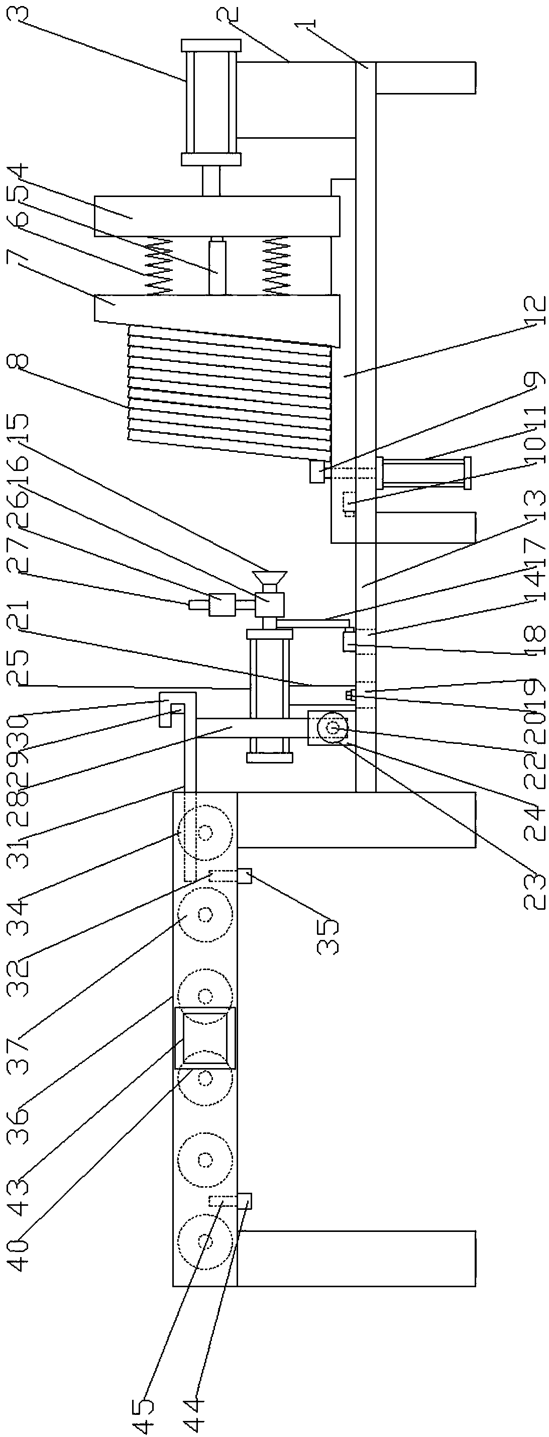
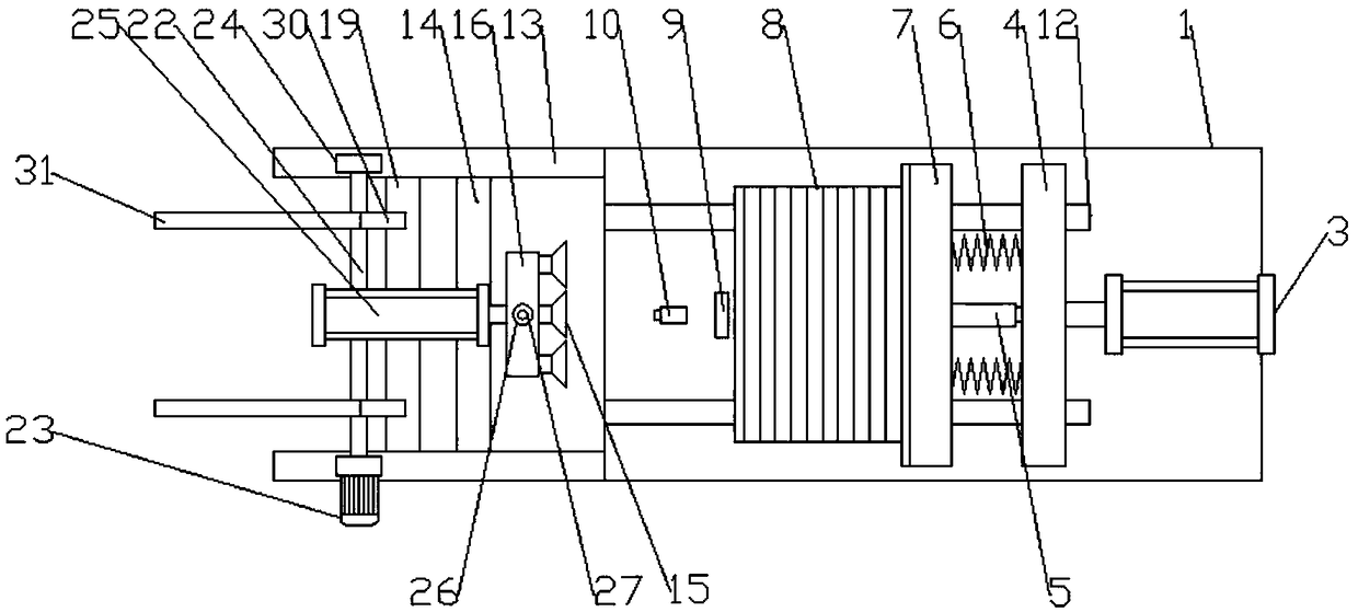
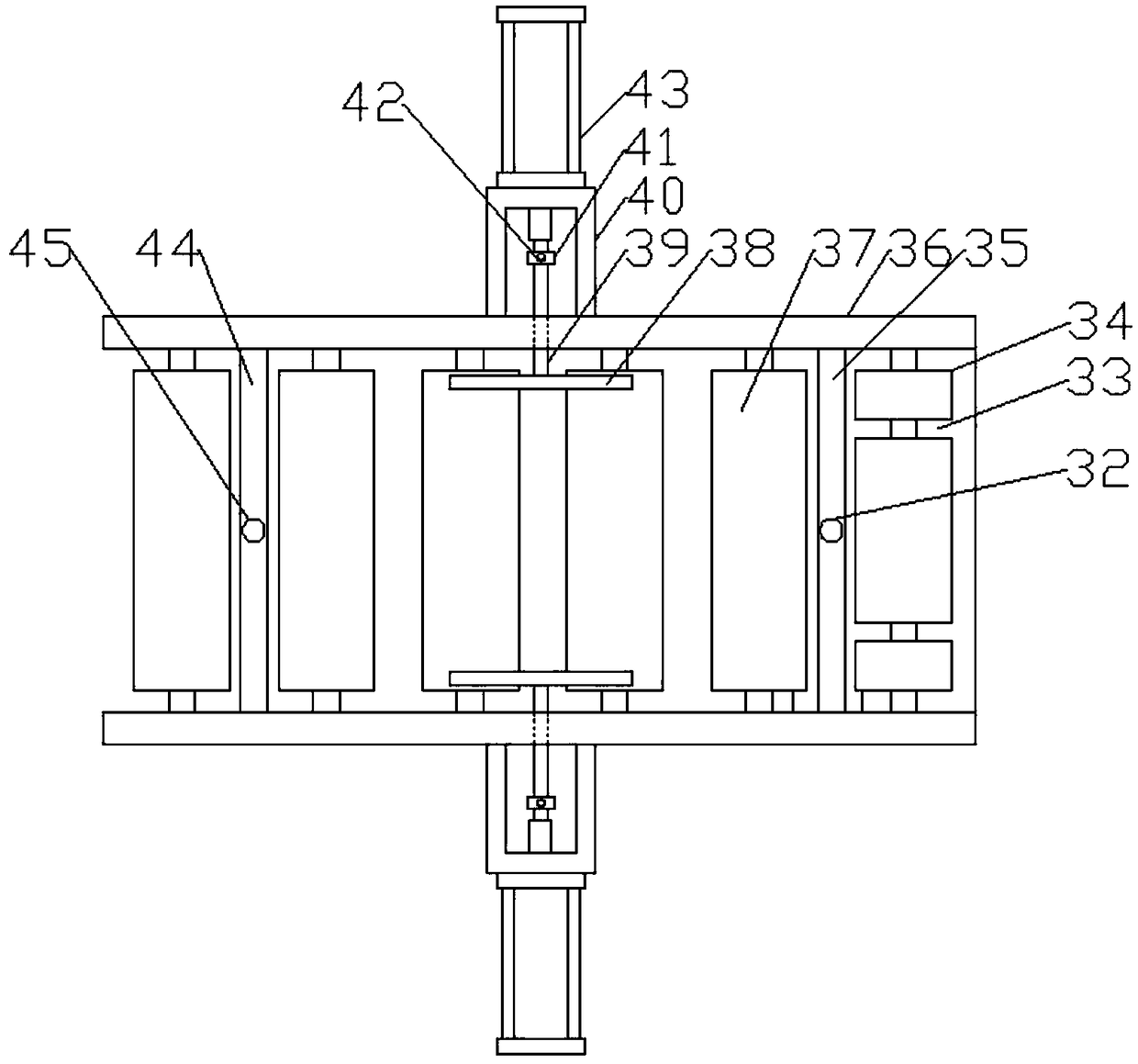
[0019] Through the description of the embodiments below, the specific implementation of the present invention includes the shape, structure, mutual position and connection relationship between the various parts, the function and working principle of each part, the manufacturing process and the operation and use method of the various components involved. etc., to make further detailed descriptions to help those skilled in the art have a more complete, accurate and in-depth understanding of the inventive concepts and technical solutions of the present invention. ", "Bottom", "Front", "Back", "Left", "Right", "Inner", "Outer", "Side", etc., are only for reference to the direction and position of the attached drawing, therefore, the used The terms of direction and position are used to illustrate and understand the present invention, but not to limit the present invention.

[0020] Such as Figure 1-5 As shown, the present invention is a feeding device for PCB boards, comprising a...


PUM


Abstract

The invention discloses a feeding device for PCBs. The feeding device comprises a conveying frame and a placing frame located on one side of the conveying frame, two parallel sliding rails are arranged at the upper end of the placing frame, a backup plate is arranged at the upper ends of the sliding rails, a propelling device is arranged on the right side of the backup plate, a PCB stack is placedon the left side of the backup plate, a second air cylinder is fixed at the lower end of the placing frame, a pressing strip is arranged at the upper end of a piston rod of the second air cylinder, two parallel longitudinal supports are arranged on the right side of the placing frame in an extending mode, mounting side plates are arranged at the upper ends of the left sides of the longitudinal supports, a rotating shaft is arranged between the mounting side plates, a motor is further arranged on one mounting side plate, an output shaft of the motor is connected with the rotating shaft, a turnover device is arranged on the rotating shaft, second transverse supports are fixed on the portion, on the right side of the motor, of the longitudinal supports, and the middles of the upper ends of the second transverse supports are provided with a transferring device. According to the feeding device, the PCBs are taken out one by one, are conveyed to the turnover device through the transferringdevice, are conveyed to the conveying frame through the turnover device, and are corrected through a correcting device, manual work is replaced for transferring, so that the labor amount of workers isreduced, the feeding time is shortened, and the feeding efficiency is improved.

Description

technical field [0001] The invention belongs to the technical field of PCB board production, and in particular relates to a PCB board feeding device. Background technique [0002] In the production line of PCB boards, PCB boards need to go through multiple processing procedures. Due to the limitations of the production workshop site, PCB boards usually need to be manually transported to the next process after being processed in the previous process. PCB boards are piled up layer by layer, and the stacked PCB boards are manually taken to the next production line, and then placed one by one on the conveyor device of the production line, resulting in a very cumbersome process of transferring and loading PCB boards and wasting a lot of time. Contents of the invention [0003] According to the deficiencies of the prior art above, the technical problem to be solved by the present invention is to provide a PCB board feeding device to solve all or one of the above-mentioned defect...

Claims


Application Information

Patent Timeline
IPC IPC(8): B65G47/248B65G47/91
CPCB65G47/248B65G47/914B65G47/918B65G2201/0217
Inventor 张雷赵守江姜广彪张琳胡洪波
Owner ANHUI SHENZE ELECTRONICS TECH
Learn More