Energy-saving coal gasification reacting furnace and method

A reaction furnace and coal gasification technology, which is applied in the field of coal gasification, can solve the problems of no independent installation, multiple energy sources, energy waste, etc., and achieve the effect of reasonable design and high practicability

Pending Publication Date: 2019-02-22
HAMKOO TECH DALIAN
View PDF1 Cites 4 Cited by
  • Summary
  • Abstract
  • Description
  • Claims
  • Application Information

AI Technical Summary

Problems solved by technology

[0002] The patent application publication number CN 206955962U discloses a high-efficiency reaction furnace for coal gasification, which can greatly improve the energy utilization efficiency of the equipment, reduce production costs, and achieve the purpose of energy saving and environmental protection by adopting a preheating recovery device. However, there are still some shortcomings in the actual implementation of this technical solution. For example, there is no independent oxidant heating equipment. In order to provide heat during the initi

Method used


Image

  • Energy-saving coal gasification reacting furnace and method
  • Energy-saving coal gasification reacting furnace and method
  • Energy-saving coal gasification reacting furnace and method

Examples


Embodiment 1

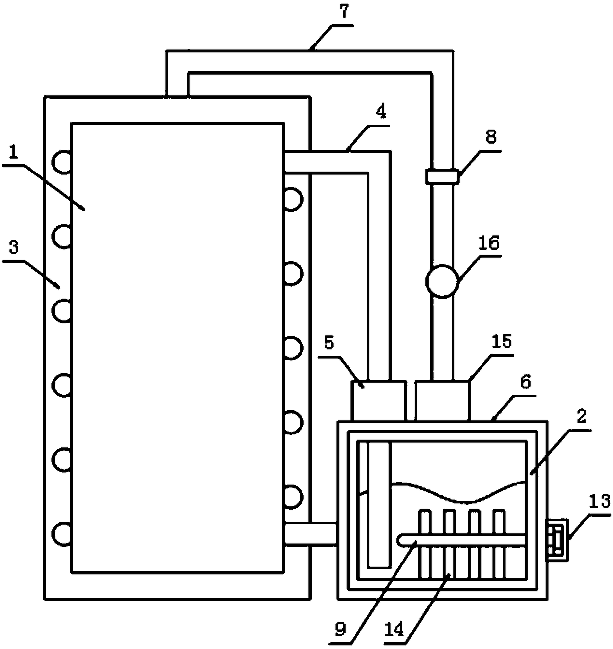
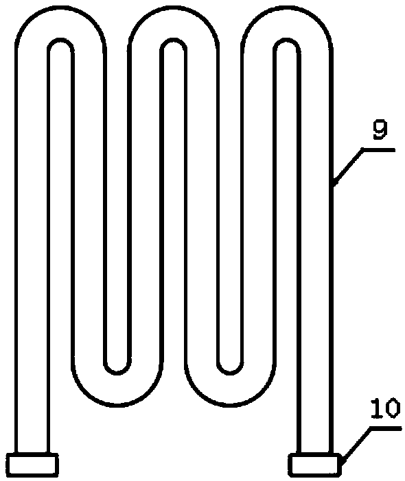
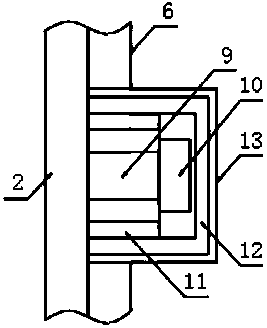
[0026] The present invention provides such as Figure 1-3 The shown energy-saving coal gasification reaction furnace includes a reaction furnace body 1 and a steam supply chamber 2, the steam supply chamber 2 is arranged on one side of the reaction furnace body 1, and a spiral heat exchange tube is arranged on the outside of the reaction furnace body 1 4. The spiral heat exchange tube 4 is provided with a pumping unit 5, the top of the steam supply chamber 2 is provided with a steam discharge pipe 7, and the steam discharge pipe 7 is provided with a steam delivery unit 15 and a gas flow metering unit 16 and the pipeline opening and closing unit 8, the inside of the steam supply chamber 2 is provided with a serpentine heat exchange tube 9, the end of the serpentine heat exchange tube 9 is provided with an inner connector 10, and the outer side of the inner connector 10 is provided with a connection A ring 11, the connecting ring 11 is fixed on the side of the steam supply chamb...

Embodiment 2

[0036] An energy-saving coal gasification reaction method, comprising the energy-saving coal gasification reaction furnace, further comprising the following steps;

[0037] S1: energize the heating element 14, and heat the oxidant and water in the steam supply chamber 2 after the heating element 14 is energized;

[0038] S2: After heating, the water turns into water vapor and enters the reaction furnace body 1 through the steam discharge pipe 7;

[0039]S3: When the gas flow metering unit 16 starts counting, cut off the power supply of the heating element 14;

[0040] S4: start the reaction furnace body 1 and feed the fly ash into the reaction furnace body 1, and the water vapor and the fly ash are combined into water gas in the reaction furnace body 1;

[0041] S5: the pumping unit 5 pumps the water inside the steam supply chamber 2 into the 4, and the water exchanges heat with the reaction furnace body 1;

[0042] S6: The heat energy generated by the reaction furnace body ...


PUM


Abstract

The invention discloses an energy-saving coal gasification reacting furnace and method. The energy-saving coal gasification reacting furnace comprises a reacting furnace body and a steam supply cavity, wherein the steam supply cavity is arranged on one side of the reacting furnace body, and the outside of the reacting furnace body is provided with a spiral heat exchange tube which is provided witha water pumping unit; the top of the steam supply cavity is provided with a steam discharging pipe which is provided with a steam conveying unit, a gas flow metering unit and a pipe opening and closing unit; the inside of the steam supply cavity is provided with a snake-like heat exchange pipe, the end portion of the snake-like heat exchange pipe is provided with an internal joint, the outside ofthe internal joint is provided with a connecting ring fixed onto the side surface of the steam supply cavity, a sealing cover is connected in a sleeve mode outside the connecting ring, and the innerwall of the steam supply cavity is provided with a heating element. The energy-saving coal gasification reacting furnace avoids an idle state of the reacting furnace body to maximize energy-saving effects, and meanwhile, is reasonable in design and high in practicality.

Description

technical field [0001] The invention relates to the technical field of coal gasification, in particular to an energy-saving coal gasification reaction furnace and a method. Background technique [0002] The patent application publication number CN 206955962U discloses a high-efficiency reaction furnace for coal gasification, which can greatly improve the energy utilization efficiency of the equipment, reduce production costs, and achieve the purpose of energy saving and environmental protection by adopting a preheating recovery device. However, there are still some shortcomings in the actual implementation of this technical solution. For example, there is no independent oxidant heating equipment. In order to provide heat during the initial operation of the equipment to make the oxidant, that is, water, heated and evaporated into water vapor, it is necessary to make the equipment idle for a certain period of time, and the equipment idles. At the same time, it will consume mor...

Claims


Application Information

Patent Timeline
IPC IPC(8): C10J3/48C10J3/72
CPCC10J3/48C10J3/72C10J2300/1246C10J2300/0933Y02P20/10
Inventor 王超
Owner HAMKOO TECH DALIAN
Why Eureka
Try Eureka