Check patentability & draft patents in minutes with Patsnap Eureka AI!

Cross arm assembly and power transmission rod

A cross-arm and assembly technology, applied in the field of cross-arm assemblies and transmission poles, can solve the problems of being difficult to apply to various types of poles, affecting the bearing capacity and service life of the cross-arm, affecting the service life of the cross-arm, etc. Improve service life and facilitate disassembly and maintenance

Pending Publication Date: 2019-02-22
JIANGSU SHENMA ELECTRIC CO LTD
View PDF0 Cites 1 Cited by
  • Summary
  • Abstract
  • Description
  • Claims
  • Application Information

AI Technical Summary

Problems solved by technology

When the cross arm is directly connected to the rod body, holes need to be drilled on the cross arm, which will affect the bearing capacity and life of the cross arm
When connecting through the connecting plate, a variety of accessories are needed for assistance, and the fixing of the cross arm and the connecting plate affects the service life of the cross arm and is not easy to maintain
[0003] Most of the existing connecting plates are customized for specific rod bodies, without versatility, it is difficult to apply to many different types of rod bodies

Method used


Image

  • Cross arm assembly and power transmission rod
  • Cross arm assembly and power transmission rod
  • Cross arm assembly and power transmission rod

Examples


Embodiment 1

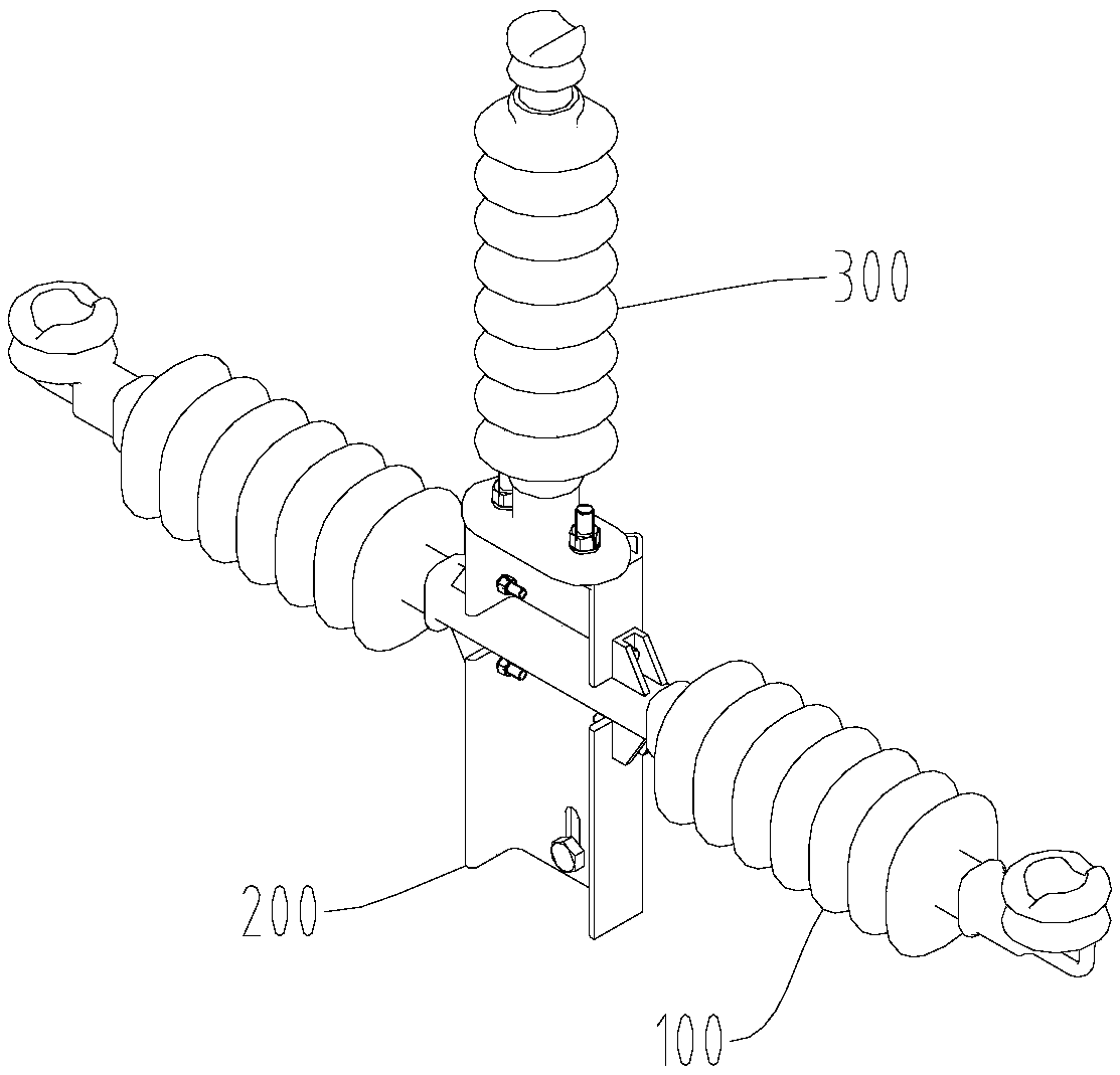
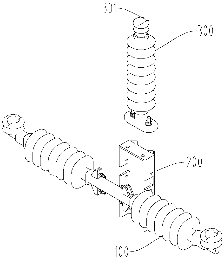
[0046] like Figure 1A ~ Figure 4 As shown, in the cross-arm assembly of this embodiment, the two opposite side walls of the transition plate 200 are provided with locking grooves 201 , and the interior of the transition plate 200 is hollow. Connecting holes 202 are respectively provided above and below the card slot 201 .

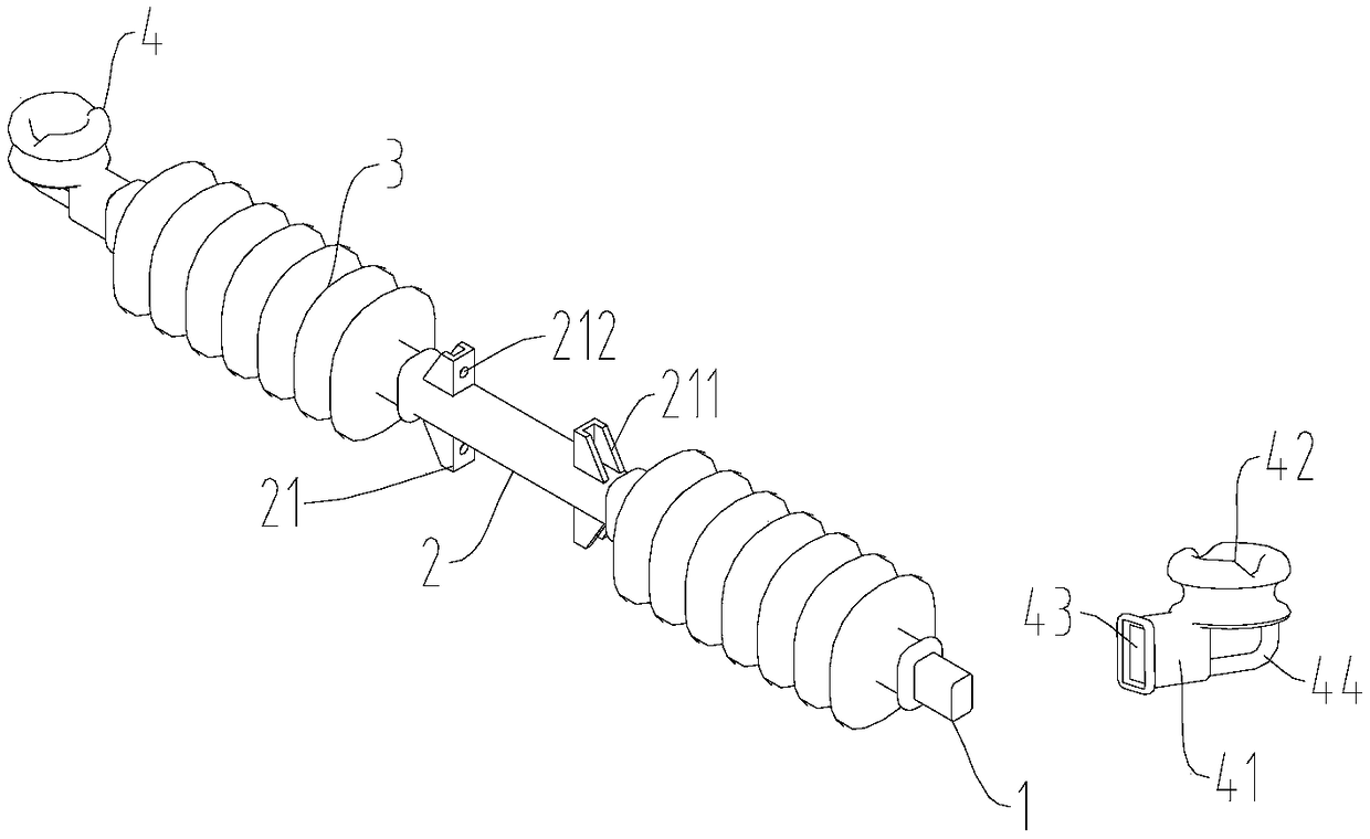
[0047] The upper surface and the lower surface of the sleeve 2 are respectively provided with connecting ears, and the connecting ears are first connecting ears 21 . The upper surface and the lower surface of the sleeve 2 are symmetrically provided with first connecting ears 21 , and the number of the first connecting ears 21 is four in total. The first connecting ear 21 extends upward from the upper surface of the sleeve 2 or downward from the lower surface. A connecting hole 212 is formed on the first connecting ear 21 . The sleeve 2 is installed in the slot 201 , the connection hole 202 corresponds to the connection hole 212 , the first connection ea...

Embodiment 2

[0056] like Figure 5 As shown, the structure of the cross-arm assembly of this embodiment is similar to that of Embodiment 1. The difference is that, in order to facilitate the erection of three-phase power transmission lines, this embodiment does not use the top-phase cross-arm, but adds a middle pole to the cross-arm. The phase conductor is fixed to terminal 5. There is a certain distance between the middle-phase wire fixing terminal 5 and the wire fixing terminal 4, which can ensure a safe distance between adjacent wires.

[0057] In order to facilitate the installation of the fixed terminal 5 of the middle-phase wire, the insulating layer 3 includes a long insulating layer 31 and a short insulating layer 32 . The long insulating layer 31 is located on one side of the sleeve 2 , and a plurality of short insulating layers 32 are located on the other side of the sleeve 2 , and the number of the short insulating layers 32 in this embodiment is two. The middle-phase wire fix...

Embodiment 3

[0059] like Image 6 and Figure 7 As shown, the structure of the cross-arm assembly in this embodiment is similar to that in Embodiment 1, the difference is that the front wall of the transition plate in this embodiment extends from the horizontal upper connecting plate 206 and the lower connecting plate 207 . A gap is provided between the upper connecting plate 206 and the lower connecting plate 207 .

[0060] The upper surface and the lower surface of the sleeve 2 are respectively provided with connecting ears, and the connecting ears are the second connecting ears 22 . The second connecting ear 22 is provided with a vertical connecting hole 221 , and the second connecting ear 22 is connected to the transition plate through the connecting hole 221 . The sleeve 2 is installed between the upper connecting plate 206 and the lower connecting plate 207 , the upper second connecting ear 22 is fixedly connected with the upper connecting plate 206 , and the lower second connectin...


PUM


Abstract

The invention discloses a cross arm assembly and a power transmission rod. The cross arm assembly includes a cross arm and a transition plate, the cross arm includes a mandril, a sleeve, insulating layers and wire fixing terminals, the sleeve is fixedly connected to the middle of the mandril, the mandril is coated with the insulating layers, the left and right sides of the sleeve are provided withthe insulating layers correspondingly, both ends of the mandril are provided with the wire fixing terminals, the outer wall of the sleeve is provided with connecting lugs, the cross arm is fixedly connected with the transition plate through the connecting lugs. The cross arm assembly has simple structure, convenient installation and maintenance, and can be suitable for a variety of rod bodies.

Description

technical field [0001] The invention belongs to the technical field of power transmission equipment, and in particular relates to a novel cross-arm component and a power transmission pole. Background technique [0002] The crossarm is fixedly connected with the transmission pole body in the transmission line, and is used as a part to support the wires to ensure that the specified safety distance is maintained between the wires. When the cross arm is connected with the rod body, the cross arm is either directly fixed on the rod body, or the cross arm is connected with the rod body through a connecting plate. When the cross arm is directly connected with the rod body, holes need to be drilled on the cross arm, which affects the bearing capacity and life of the cross arm. When connecting through the connecting plate, various accessories are needed for assistance, and the fixing of the cross arm and the connecting plate affects the service life of the cross arm and is inconveni...

Claims


Application Information

Patent Timeline
IPC IPC(8): E04H12/24E04H12/00
CPCE04H12/00E04H12/24
Inventor 马斌李德权徐康刘超郁杰黄清
Owner JIANGSU SHENMA ELECTRIC CO LTD
Features
  • R&D
  • Intellectual Property
  • Life Sciences
  • Materials
  • Tech Scout
  • Unparalleled Data Quality
  • Higher Quality Content
  • 60% Fewer Hallucinations
Learn More