Automatic control system of rainproof cloth for open grain stack

An automatic control system and control system technology, applied in tents/canopies, building types, buildings, etc., can solve problems such as difficulty in preventing rain in open-air grain stacks

Pending Publication Date: 2019-02-22
TIANJIN UNIV OF TECH & EDUCATION TEACHER DEV CENT OF CHINA VOCATIONAL TRAINING & GUIDANCE
0 Cites 2 Cited by

AI-Extracted Technical Summary

Problems solved by technology

[0003] The purpose of the present invention is to provide an automatic control system for the rain-proof cloth of the open-air grain stack in order to solve the probl...

Abstract

The invention discloses an automatic control system of rainproof cloth for an open grain stack. The automatic control system includes a contraction and expansion mechanical structure and a control system, the contraction and expansion mechanical structure includes an outer tooth ring fixedly arranged on the outer edge of the top end of the cylindrical grain stack, a gear connected with the outer tooth ring in an engaged mode and driven by a stepping motor, and a rainproof cloth reel fixedly mounted with the gear in the same axle center and parallel to the axis of the grain stack, one edge of the rainproof cloth is fixed to the circumferential outer wall of the cylindrical grain stack, and the other edge of the rainproof cloth is fixed to the rainproof cloth reel.

Application Domain

Tents/canopies

Technology Topic

Automatic controlControl system +1

Image

  • Automatic control system of rainproof cloth for open grain stack
  • Automatic control system of rainproof cloth for open grain stack
  • Automatic control system of rainproof cloth for open grain stack

Examples

  • Experimental program(3)
  • Effect test(1)

Example Embodiment

[0040] Example 1
[0041] An automatic control system for open-air grain stack rainproof cloth, including unwinding mechanical structure and control system;
[0042] Such as Figure 12-14 As shown, the unfolding mechanical structure includes an outer gear ring 1 fixedly arranged on the outer edge of the top end of the cylindrical grain stack 6 in meshing connection with the outer gear ring 1 and driven by the stepping motor 3. Gear 2, and a rain-proof cloth reel 4 fixed coaxially with the gear 2 and parallel to the axis of the grain stack 6, one edge of the rain-proof cloth is fixed on the outer wall of the cylindrical grain stack The other edge is fixed on the rain-proof cloth reel;
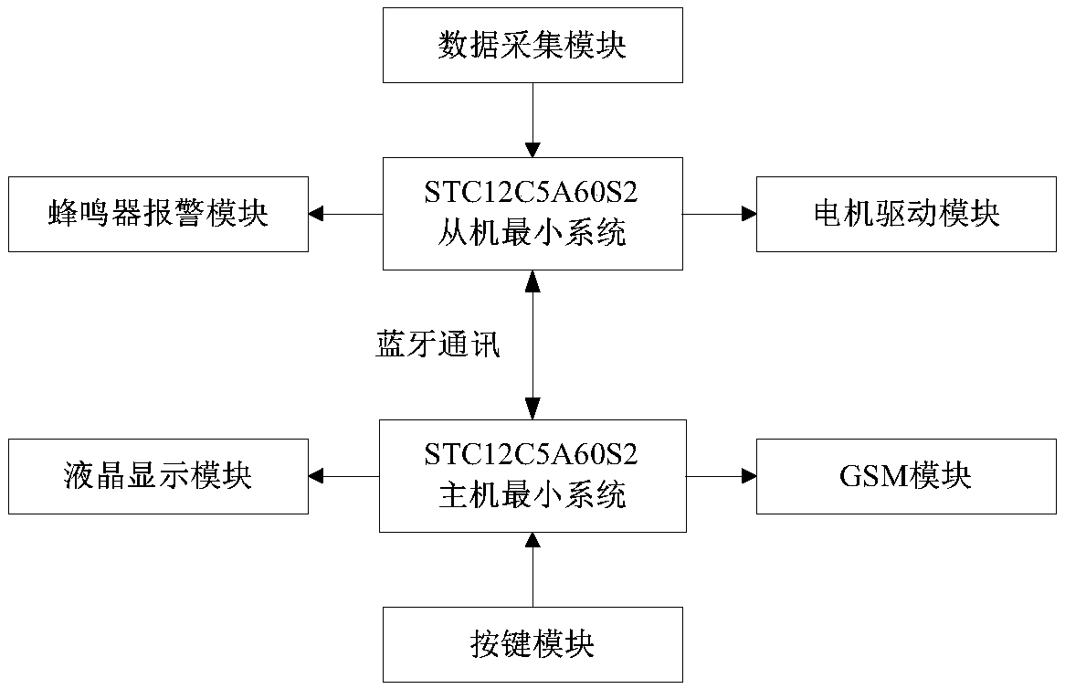
[0043] Such as figure 1 As shown, the control system includes a master unit and a slave unit that are communicatively connected through a Bluetooth module; the slave unit includes a slave control module, an alarm module for generating an alarm signal, and an alarm module for collecting air temperature, air humidity and humidity. , A data acquisition module for light intensity and rainfall conditions, and a motor drive module for driving the deployment of the rainproof cloth. The alarm module and the motor drive module are respectively communicatively connected with the output end of the slave control module, and the data acquisition module is connected with The input end of the slave control module is connected to the communication;
[0044] The host unit includes a host control module wirelessly connected to the slave control module, a GSM communication module used to transmit the alarm signal to the user's mobile phone, and used to display air temperature, air humidity, light intensity, rainfall status, and The display module of the switch state of the rainproof cloth and the button module, the GSM communication module and the display module are respectively communicatively connected with the output end of the host control module, and the button module is communicatively connected with the input end of the host control module, Said.
[0045] Way of working:
[0046] Taking the tooth surface of the outer gear ring 1 as the outside, and the inner smooth part of the outer gear ring 1 as the inside, the gear 2 is connected to the output shaft of the stepping motor 3 through a reduction box 6. The bottom of the reduction box 6 is provided with a slider 7 which abuts against the inner side of the outer gear ring 1 to form a support, and the slider 7 cooperates with the cylindrical surface on the inner side of the outer gear ring 1 for fixing.
[0047] The stepping motor 3 drives the gear 2 to move in a circular trajectory along the outer circumference of the outer gear ring 1, so that while the rain cloth reel 4 rotates along the outer circumference of the grain stack, the rain cloth reel 4 rotates. During the forward rotation of the rain cloth reel 4, the rain cloth wrapped around the outer wall of the cylindrical grain stack can be wound onto the rain cloth reel 4 shaft (the rain cloth is stowed and dried). During the reverse rotation of the rain-proof cloth reel 4, the rain-proof cloth wound on the rotating shaft of the rain-proof cloth reel 4 can be put down, so that it can be wrapped around the outer wall of the cylindrical grain stack (the rain cloth is unfolded, and the Rainproof).
[0048] The size of the gear 2 can be determined according to the thickness of the rainproof cloth. When the rainproof cloth is thicker, rotate the larger gear 2 so that the distance between the rainproof cloth reel 4 and the grain stack can accommodate the windproof cloth. The thickness of the rain cloth.
[0049] The data acquisition module collects the air temperature, air humidity and humidity, light intensity and rainfall status information of the environment where the open-air grain stack is located, and transmits these information to the slave control module. At the same time, the slave control module transmits the information to the Host control module, real-time display through the display module.
[0050] When the above indicators exceed the preset range, the alarm module gives an alarm, and the motor drive module drives the rainproof cloth to unfold to cover the grain stack. The host control module transmits alarm information to the mobile phone through the GSM communication module.
[0051] As a preferred mode, the slave control module is a slave single-chip microcomputer, and the slave single-chip microcomputer is an STC12C5A60S2 single-chip microcomputer. The host control module is a host microcontroller, and the host microcontroller is an STC12C5A60S2 microcontroller.

Example Embodiment

[0052] Example 2
[0053] This embodiment further optimizes the Bluetooth module on the basis of Embodiment 1.
[0054] The Bluetooth module includes a host Bluetooth communication module and a slave Bluetooth communication module, the model of the host Bluetooth communication module is HC-06, and the RXD end of the host Bluetooth communication module is connected to the P3.1 pin of the host microcontroller The TXD end is connected to the P3.0 pin of the host single-chip microcomputer, the model of the slave Bluetooth communication module is HC-06, and the RXD end of the slave Bluetooth communication module is connected to the P3.1 input of the slave single-chip microcomputer Pin and TXD end are connected to the P3.0 pin of the slave MCU, and the interface circuit is as follows Figure 8 Shown.

Example Embodiment

[0055] Example 3
[0056] In this embodiment, on the basis of the first embodiment, the host part and the slave part are further optimized.

PUM

no PUM

Description & Claims & Application Information

We can also present the details of the Description, Claims and Application information to help users get a comprehensive understanding of the technical details of the patent, such as background art, summary of invention, brief description of drawings, description of embodiments, and other original content. On the other hand, users can also determine the specific scope of protection of the technology through the list of claims; as well as understand the changes in the life cycle of the technology with the presentation of the patent timeline. Login to view more.
Why Eureka
Try Eureka