Supercharge Your Innovation With Domain-Expert AI Agents!

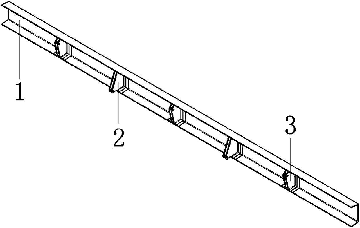
Composite material integral beam

A composite material, integrated technology, applied in aircraft assembly, aircraft parts, fuselage and other directions, can solve the problems of increasing structural weight, manufacturing assembly difficulty and manufacturing cost, reducing structural fatigue life and structural efficiency, and reducing structural fatigue life, etc. Achieve the effect of improving structural efficiency and fatigue life, reducing the number of fasteners, and reducing assembly difficulty

Inactive Publication Date: 2019-02-26
XIAN AIRCRAFT DESIGN INST OF AVIATION IND OF CHINA
View PDF0 Cites 0 Cited by
  • Summary
  • Abstract
  • Description
  • Claims
  • Application Information

AI Technical Summary

Problems solved by technology

When the composite material structure is used for the suspension joint and the steering joint, although electrochemical corrosion at the assembly interface between the joint and the composite beam can be avoided, multiple tooling molds are required for the composite material molding of the suspension joint and the steering joint, which increases the manufacturing cost
Secondly, when they are assembled with the beam, not only a large number of metal fasteners are required, but also the coordination of the assembly of the suspension joint and the steering joint requires strict design compensation and process compensation, and the fatigue life of the structure is reduced due to the mechanical connection
This will not only increase structural weight, manufacturing assembly difficulty and manufacturing cost, but also reduce structural fatigue life and structural efficiency

Method used


Image

  • Composite material integral beam
  • Composite material integral beam
  • Composite material integral beam

Examples


Embodiment Construction

[0015] In order to make the objectives, technical solutions and advantages of the present invention clearer, the technical solutions in the embodiments of the present invention will be described in more detail below in conjunction with the drawings in the embodiments of the present invention. In the drawings, the same or similar reference numerals denote the same or similar elements or elements having the same or similar functions throughout. The described embodiments are some, but not all, embodiments of the invention. The embodiments described below by referring to the figures are exemplary and are intended to explain the present invention and should not be construed as limiting the present invention. Based on the embodiments of the present invention, all other embodiments obtained by persons of ordinary skill in the art without creative efforts fall within the protection scope of the present invention.

[0016] The composite material integral beam of the present invention ...


PUM


Abstract

The invention provides a composite material integral beam, which comprises a trough beam (1), a plurality of operation joints (2) and a plurality of suspension joints (3), wherein the trough beam, theoperation joints and the suspension joints are integrally molded, the trough beam (1) comprises a web plate, an upper flange and a lower flange, the upper flange and the lower flange are vertically connected to the web plate, one side, connected to the flange, of the web plate of the trough beam (1) is embedded with the plurality of the operation joints (2) and the plurality of the suspension joints (3), the operation joint (2) has a double-lug sheet structure, each lug sheet comprises a first flat plate and a right-angled triangular plate forming butt joint with the first flat plate, the first flat plate is connected to one right-angled edge in the right-angled triangular plate, the other right-angled edge in the right-angled triangular plate is positioned on one side of the upper flange, the suspension joint (3) has a double-lug sheet structure, each lug sheet comprises a second flat plate and a obtuse-angled triangular plate forming butt joint with the second flat plate, the secondflat plate is connected to the longest edge in the obtuse-angled triangular plate, and the shortest edge in the obtuse-angled triangular plate is positioned on one side of the lower flange. The composite material integral beam of the present invention has advantages of structural weight reducing, reduced number of fasteners, manufacturing cost reducing and fatigue life improving.

Description

technical field [0001] The invention belongs to the field of aircraft structure design, and in particular relates to a composite material integral beam. Background technique [0002] Nowadays, with the development and application of composite material technology, the skins, beams, ribs, etc. alloy and titanium alloy construction. [0003] When the suspension joints and manipulation joints are made of metal materials, certain anti-corrosion measures need to be taken between them and the composite material structural beams to avoid electrochemical corrosion at the metal-composite material interface. When the composite material structure is used for the suspension joint and the steering joint, although the electrochemical corrosion at the assembly interface between the joint and the composite material beam can be avoided, multiple tooling molds are required to form the composite material of the suspension joint and the steering joint, which increases the manufacturing cost. S...

Claims


Application Information

Patent Timeline
Patent Type & Authority Applications(China)
IPC IPC(8): B64C1/06
CPCB64C1/064B64F5/10Y02T50/40
Inventor 丁怡凡玉
Owner XIAN AIRCRAFT DESIGN INST OF AVIATION IND OF CHINA
Features
  • R&D
  • Intellectual Property
  • Life Sciences
  • Materials
  • Tech Scout
  • Unparalleled Data Quality
  • Higher Quality Content
  • 60% Fewer Hallucinations
Learn More