Water washing device

A washing device and pool technology, which is applied in the direction of water treatment and refining, can solve the problems of complex and large equipment, non-continuous production, time-consuming efficiency, etc., and achieve the effect of increasing the washing area, speeding up the washing rate, and improving product quality

Inactive Publication Date: 2019-02-26
唐林
View PDF0 Cites 0 Cited by
  • Summary
  • Abstract
  • Description
  • Claims
  • Application Information

AI Technical Summary

Problems solved by technology

The existing equipment is complex and huge, and cannot be produced continuously. Once cleaned, oil and water need to be separated, which is time-consuming and inefficient

Method used


Image

  • Water washing device

Examples


Embodiment 1

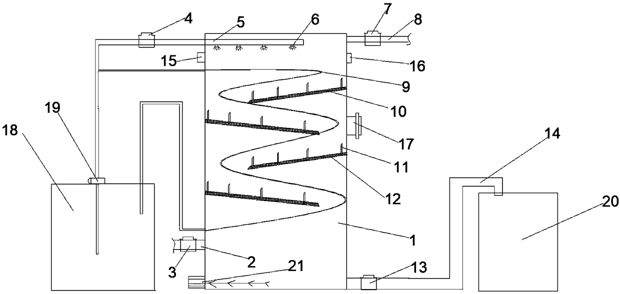
[0024] Such as figure 1 As shown, a water washing device includes a washing machine body 1, a feed pipe 2 is connected to the lower part of the outer surface of the water washing machine body 1 by bolts, a first valve 3 is connected to the bolts on the feed pipe 2, and an inlet valve 3 is connected to the upper outer wall of the water washing machine body 1 by bolts. The water pipe 5 is connected with the water inlet pipe 5 by bolts on the water inlet pipe 5, and the water inlet pipe 5 is provided with a nozzle 6 running through the body, and there are 4 nozzles 6. The material pipe 8 is bolt-connected with a third valve 7; the inside of the washing machine body 1 is provided with a deflector 10 obliquely, and the deflector 10 is provided with a baffle 11. The plate 11 is located on the upper part of the deflector 10, and the baffle 11 is arranged in a vertical direction. The deflector 10 is inclined downward, and the angle between it and the horizontal plane is preferably 30°...

Embodiment 2

[0026] Such as figure 1 As shown, this embodiment is a further optimization made on the basis of Embodiment 1. Specifically, a movable stirring motor 21 is provided at the inner lower end of the washing body 1 near the bottom, and the movable stirring motor 21 includes a stirring blade, a rotating shaft And the motor, the rotating shaft is arranged perpendicular to the side wall of the washing machine body 1, and runs through the wall of the washing machine body 1 to be connected with the motor.

[0027] In this embodiment, the water washing rate can be accelerated by setting the movable stirring motor 21 .

Embodiment 3

[0029] Such as figure 1 As shown, this embodiment is a further optimization made on the basis of Embodiment 1 and Embodiment 2. Specifically, a flange cover 17 is provided on the outside of the washing body 1, and a handle is provided on the flange cover 17; The upper end of the flange cover 17 is provided with a sampling port 16 near the discharge pipe 8 .

[0030] In this embodiment, by setting the flange cover 17, the filter screen 12 can be taken out and cleaned through the flange cover 17 when the filter screen 12 is blocked, which is convenient for maintenance of the body; by setting the sampling port 16, the washing process can be monitored in real time, so that the operator cannot judge the solution in time. Whether the solution meets the water washing standard, and the operator's misjudgment leads to incomplete washing of the solution.

[0031] working principle

[0032] Open the first valve 3 and the movable stirring motor 21 switch and close the water inlet pipe 5...


PUM


Abstract

The invention discloses a water washing device. The water washing device comprises a water washing machine body, a feed pipe is arranged at the lower part of the outer side surface of the water washing machine body, a first valve is arranged on the feed pipe, a water intake pipe is further arranged at the upper part of the feed pipe, a second valve is arranged on the water intake pipe, the water intake pipe penetrates through the machine body to be provided with sprayers, a discharge pipe is arranged at the upper part of the outer side of the water washing machine body, a third valve is arranged on the discharge pipe; a flow guide plate is arranged slantly in the inner part of the water washing machine body, a baffle is arranged on the flow guide plate and is located at the lower part of the flow guide plate, the baffle is arranged in the perpendicular direction, and a filter screen is arranged on the lower surface of the flow guide plate. The water washing device is provided with a sampling opening, so that the water washing process is monitored in real time, and the problem of insufficient water washing caused by the facts that an operation staff cannot judge whether a solution reaches the waster washing standard timely and that the operation staff misjudges is avoided.

Description

technical field [0001] The invention relates to the field of chemical equipment, in particular to a water washing device. Background technique [0002] In the chemical industry, it is necessary to measure the oil phase in real time, and the measured oil phase often contains a certain amount of water and water-soluble impurities, which need to be washed to remove impurities. The existing equipment is complex and huge, and cannot be produced continuously. Once cleaning is required, oil and water need to be separated, which is time-consuming and inefficient. Contents of the invention [0003] A water washing device, comprising a washing machine body, a feeding pipe is arranged on the lower part of the outer surface of the washing machine, a first valve is arranged on the feeding pipe, a water inlet pipe is arranged above the feeding pipe, and a second valve is arranged on the water inlet pipe. The water inlet pipe runs through the machine body and is provided with a nozzle, ...

Claims


Application Information

Patent Timeline
Patent Type & Authority Applications(China)
IPC IPC(8): C10G31/08
CPCC10G31/08
Inventor 唐林
Owner 唐林
Why Eureka
Try Eureka