
Support unit for a drive unit of a closing or protective device

A technology of protection device and drive unit, which is applied in the field of locking or protection device and anti-twist parts, which can solve the problems of driving unit removal or deactivation without great force and damage, and achieve the effect of simplifying manufacturing and avoiding subsequent processing

Active Publication Date: 2019-02-26
ACOMAX GMBH
View PDF5 Cites 0 Cited by
  • Summary
  • Abstract
  • Description
  • Claims
  • Application Information

AI Technical Summary

Problems solved by technology

[0018] This usually means that such removal or deactivation of the drive unit has to be achieved with little effort, which can cause subsequent damage

Method used


Image

  • Support unit for a drive unit of a closing or protective device
  • Support unit for a drive unit of a closing or protective device
  • Support unit for a drive unit of a closing or protective device

Examples


Embodiment Construction

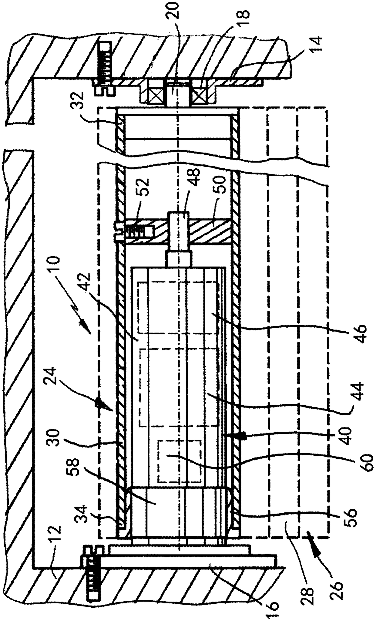
[0103] figure 1 An example embodiment of the locking device 10 is shown on the basis of a sectional illustration. The locking device 10 is designed, for example, as a rolling door, a rolling shutter, a shutter or a sectioned roller shutter / section roller shutter. The locking device 10 is fixedly accommodated on a wall 12 relative to the housing. It goes without saying that the fixing of the locking device 10 on the roof side can be effected by means of a cassette or the like. figure 1 A conventional design of a locking device 10 is shown, which is described, for example, in EP0479719B1.

[0104] exist figure 1 Among them, the locking device 10 includes a first support 14 and a second support 16, which in this embodiment are respectively accommodated on opposite walls 12, and a rolling bearing 18 is arranged in the first support 14, which supports a rotating shaft 20 .

[0105]The locking device 10 includes a shaft structure assembly 24 housed between the first seat 14 and...


PUM


Abstract

The invention relates to a support unit for housing a drive unit of a closing or protective device in an anti-torque manner. The mounting unit has a retaining member having a special-shaped housing member; and a connecting member matching the special-shaped housing member, the connecting member being connectable to a driving unit. The retaining member provides a first housing position and a secondhousing position for the connector, so that the connector can be tightened in the first housing position relative to the retaining member in the second housing position to overcome the torque. Undera force for overcoming the retaining force, the connector is movable between the first housing position and the second housing position. The invention also discloses a closing or protective device anda tool-less method for stopping the anti-torque system of the drive unit of the closing or protective device.

Description

technical field [0001] The invention relates to a mounting unit for receiving a drive unit for a locking or guarding device in a rotationally fixed manner, comprising: a holder with a receiving profile; and a connecting piece adapted to the receiving profile, connected components can be connected to the drive unit. [0002] Such a drive unit forms, for example, a component part of a shaft assembly of a roller shutter, blind or the like. According to at least some exemplary embodiments, the present invention relates to a drive unit that is integrated into a shaft assembly and is in particular arranged coaxially with the shaft assembly. [0003] Furthermore, the invention relates to a locking or guarding device, in particular a rolling door, a rolling door or a blind, having a first support, a second support and a shaft structure accommodated on the first support and the second support. components. Furthermore, the invention relates to a method for tool-free deactivation of a...

Claims


Application Information

Patent Timeline
Patent Type & Authority Applications(China)
IPC IPC(8): E06B9/17E06B9/174E06B9/42E06B9/50E06B9/72E06B9/74
CPCE06B9/17E06B9/174E06B9/42E06B9/50E06B9/72E06B9/74E06B2009/1746
Inventor 罗尔夫·瓦尔特-赛法特
Owner ACOMAX GMBH
Learn More