[0028] The technical solutions of the present invention will be clearly and completely described below in conjunction with the accompanying drawings. Obviously, the described embodiments are part of the embodiments of the present invention, rather than all of them.
[0029] The components of the embodiments of the present invention generally described and shown in the drawings herein may be arranged and designed in a variety of different configurations. Therefore, the following detailed description of the embodiments of the present invention provided in the accompanying drawings is not intended to limit the scope of the claimed invention, but merely represents selected embodiments of the present invention.
[0030] Based on the embodiments of the present invention, all other embodiments obtained by those of ordinary skill in the art without creative work shall fall within the protection scope of the present invention.
[0031] In the description of the present invention, it should be noted that the terms "center", "upper", "lower", "left", "right", "vertical", "horizontal", "inner", "outer", etc. The indicated orientation or positional relationship is based on the orientation or positional relationship shown in the drawings, and is only for the convenience of describing the present invention and simplifying the description, rather than indicating or implying that the pointed device or element must have a specific orientation or a specific orientation. The structure and operation cannot therefore be understood as a limitation of the present invention. In addition, the terms "first", "second", and "third" are only used for descriptive purposes, and cannot be understood as indicating or implying relative importance.
[0032] In the description of the present invention, it should be noted that the terms "installation", "connected" and "connected" should be understood in a broad sense, unless otherwise clearly specified and limited. For example, they can be fixed or detachable. Connected or integrally connected; it can be a mechanical connection or an electrical connection; it can be directly connected or indirectly connected through an intermediate medium, and it can be the internal communication between two components. For those of ordinary skill in the art, the specific meaning of the above-mentioned terms in the present invention can be understood in specific situations.
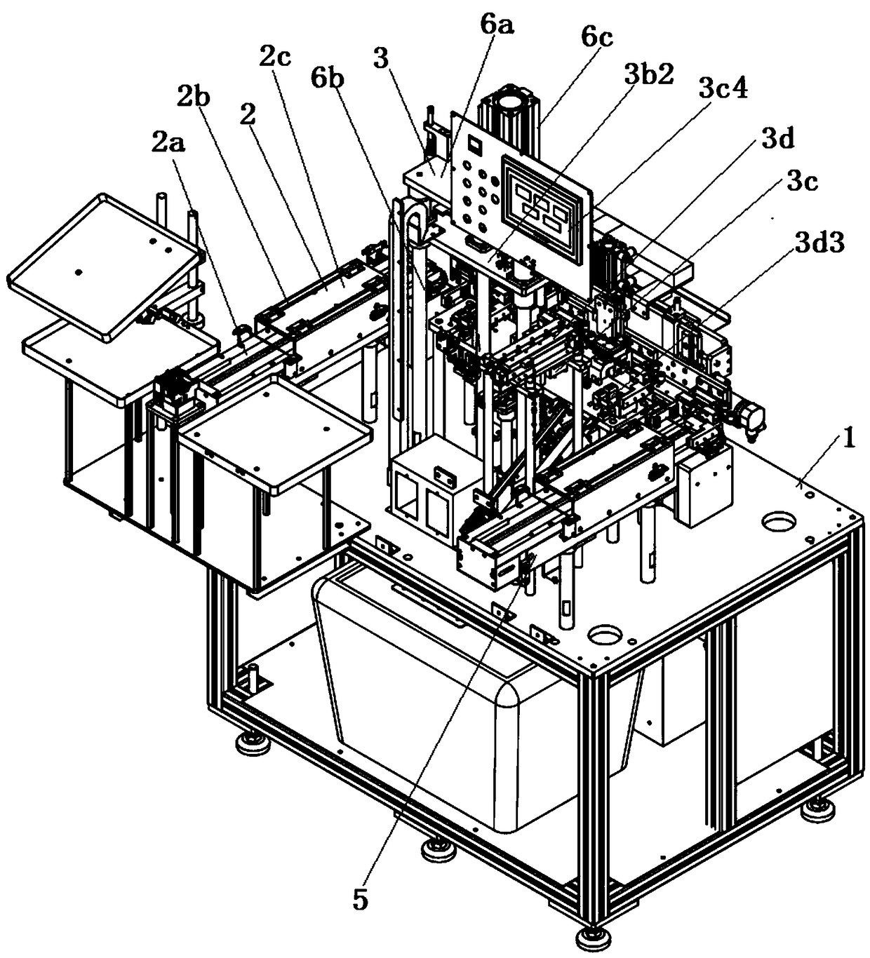
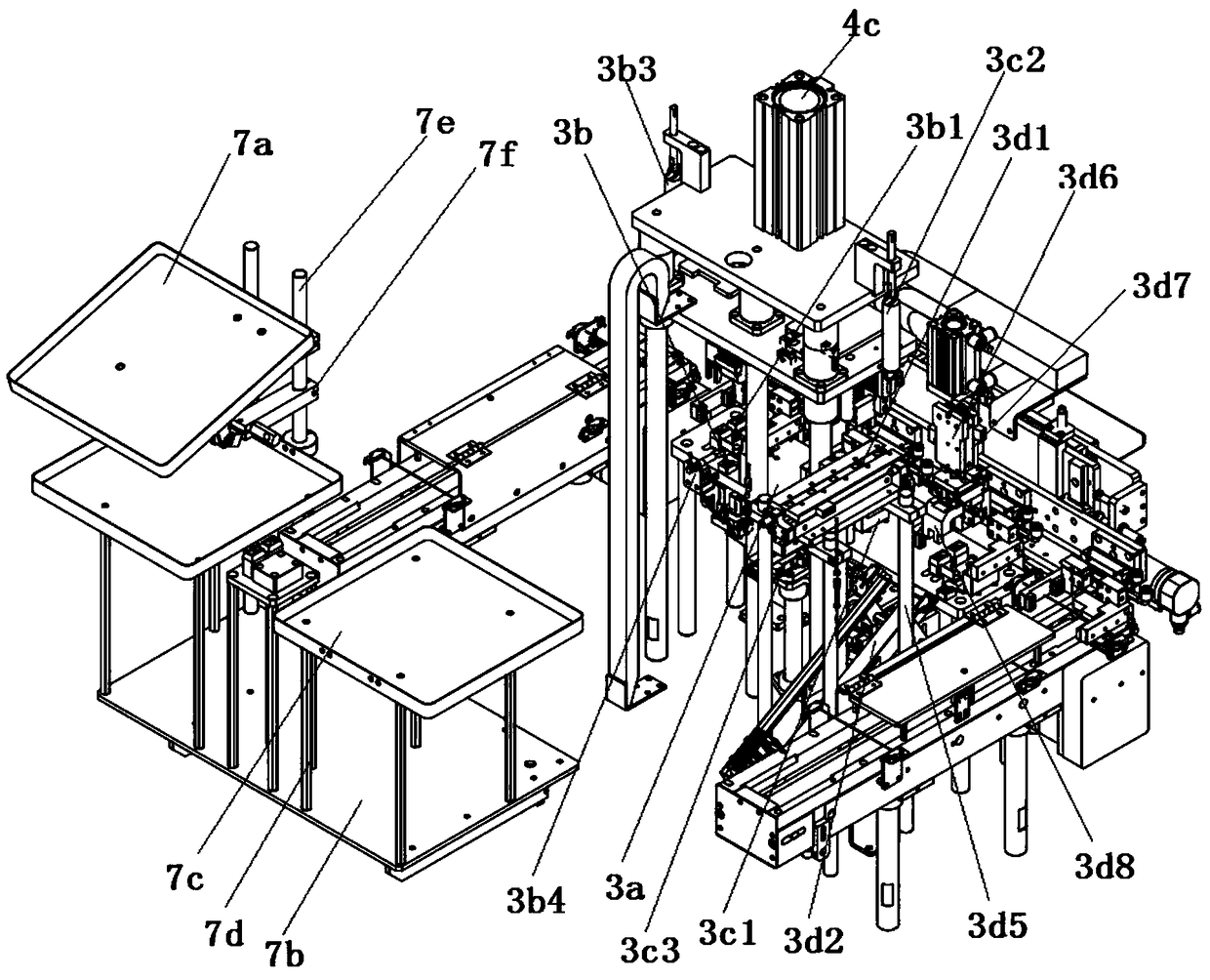
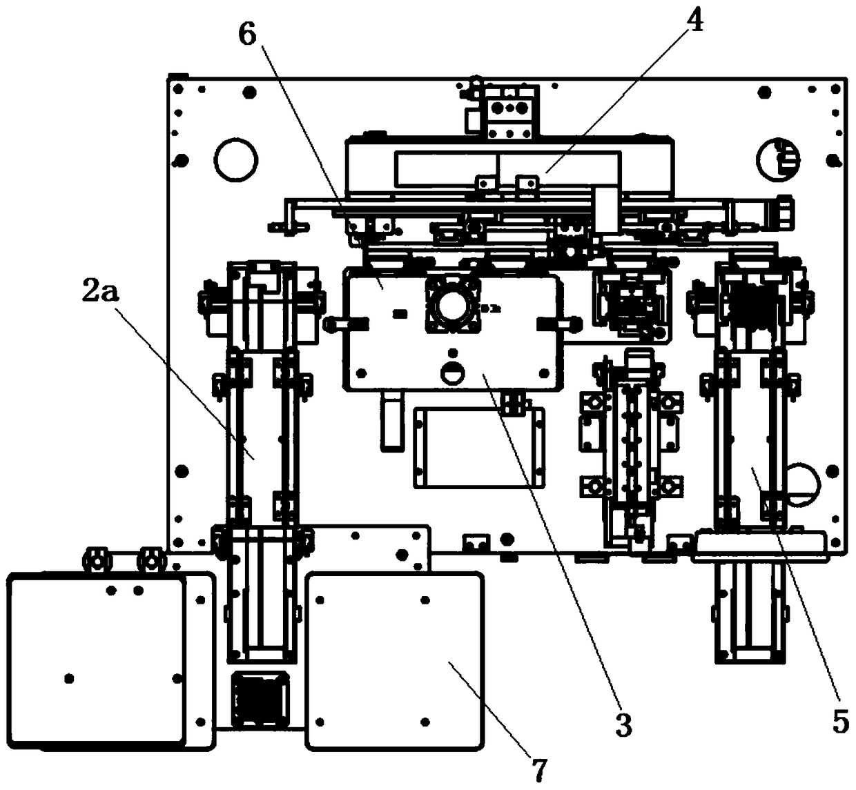
[0033] Combine below Figure 1 to Figure 6 As shown, the embodiment of the present invention provides a hardware assembly product assembly inspection equipment, including a workbench 1, a feeding mechanism 2, a detection mechanism 3, a conveying mechanism 4, and an unloading conveyor belt 5. The conveying mechanism 4 is provided Between the loading mechanism 2 and the unloading conveyor belt 5, the detection mechanism 3 is arranged on the transport mechanism 4. The detection mechanism 3 includes a support table 3a, a label detection assembly 3b, a verticality inspection assembly 3c, and unqualified The product reject assembly 3d, the support platform 3a is arranged on the side of the transport mechanism 4, the verticality check assembly 3c is arranged between the label detection assembly 3b and the defective product rejection assembly 3d, and the transport mechanism 4 includes The frame 4a, the clamping assembly 4b, the lifting assembly 4c and the pushing assembly 4d for driving the clamping assembly 4b to move in the horizontal direction, the pushing assembly 4d is arranged on the frame 4a, and the clamping assembly 4b It includes a mounting plate 4b1 with a rectangular parallelepiped structure and four first air clamps 4b2 arranged at equal intervals along the length of the mounting plate 4b1. The first air clamps 4b2 are mounted on the pushing assembly 4d. The two clamping parts are provided with two clamping blocks 4b3 arranged at intervals, and the clamping block 4b3 is provided with a non-slip layer; the workpiece can be automatically loaded by the loading mechanism 2 through the unloading conveyor belt 5. The workpiece can be automatically blanked. Through the handling mechanism 4, the workpiece can be automatically moved through the detection mechanism 3 and moved to the feeding belt, so that the workpiece can be tested in various aspects step by step. The high degree of automation is worthy of promotion. The detection mechanism 3 It can perform label inspection, vertical inspection, buckle inspection and reject unqualified products on the workpiece without manual operation by workers, which reduces the labor intensity of workers.
[0034] Further, the pushing assembly 4d includes a pushing plate 4d1 and two sliding rails 4d2 spaced apart on the side wall of the frame 4a, and each sliding rail 4d2 is provided with a sliding block 4d3 that is slidingly matched with it. The pushing plate 4d1 is installed on the side walls of the two sliding blocks 4d3, the frame 4a is provided with a pushing cylinder 4d4 arranged horizontally, and the output end of the pushing cylinder 4d4 is fixedly connected to the pushing plate 4d1 ; The pusher assembly 4d can move the clamping assembly in the horizontal direction, the pusher cylinder 4d4 can drive the pusher plate 4d1 to move, the pusher plate 4d1 can drive the mounting plate 4b1 to move, so that the mounting plate 4b1 can move in the horizontal direction , The mounting plate 4b1 can drive the four first air clamps 4b2 to move, so that the workpiece can be transported from the left to the right.
[0035] Further, the lifting assembly 4c includes a lifting cylinder 4c1 and two vertical guide rails 4c2 arranged on the pushing plate 4d1 at intervals, and each of the guide rails 4c2 is provided with a lifting block 4c3 slidably engaged with it. The mounting plate 4b1 is fixed on the side walls of the two lifting blocks 4c3, and the output end of the lifting cylinder 4c1 is provided with a connecting block 4c4 fixedly connected to the top of the mounting plate 4b1; the lifting cylinder 4c1 can drive the connecting block 4c4 when working Moving in the vertical direction, the connecting block 4c4 can drive the mounting plate 4b1 to move, so that the mounting plate 4b1 can be raised and lowered in the vertical direction, and the mounting plate 4b1 can drive the four first air clamps 4b2 to rise and fall to make the first air clamp 4b2 can be lifted to a suitable height to clamp the workpiece.
[0036] Further, the label detection assembly 3b includes a detection jig 3b1, a lifting plate 3b2, and a material lifting component 6 that drives the lifting plate 3b2 to move in the vertical direction provided on the top of the support platform 3a. The lifting plate 3b2 There is a label detection sensor 3b3 on the left side, and a buckle sensor 3b4 is installed on the side wall of the support platform 3a; when the workpiece moves to the label detection assembly 3b, the transport mechanism 4 can place the workpiece on the detection jig 3b1, The pushing cylinder 6c can push the lifting plate 3b2 to move, so that the label detection sensor 3b3 on the left side of the lifting plate 3b2 can be lifted to an appropriate height, so that the label detection sensor 3b3 can detect the label on the workpiece, and the sensor 3b4 The work piece can be buckled and detected, and the label detection sensor 3b3 and the buckle sensor 3b4 can transmit the detected data to the display screen 3c4 in the form of electrical signals.
[0037] Further, the material lifting component 6 includes a fixing plate 6a and four supporting columns 6b arranged in a matrix and fixed at the bottom of the fixing plate 6a. The lifting plate 3b2 is slidably sleeved on the supporting columns 6b, and the fixing The top of the plate 6a is provided with a pushing cylinder 6c with the output end facing downwards. The output end of the pushing cylinder 6c is fixedly connected with the top of the lifting plate 3b2; the work of the sending cylinder can push the lifting plate 3b2 to move, so that the lifting plate 3b2 is left The label detection sensor 3b3 on the side can be raised and lowered to a suitable height, so that the label detection sensor 3b3 can detect the label on the workpiece.
[0038] Further, the verticality inspection assembly 3c includes a limit jig 3c1, a verticality detection sensor 3c2 and a support frame arranged on the top of the support platform 3a, and the verticality detection sensor 3c2 is arranged on the right side of the lifting plate 3b2, The top of the support frame is provided with a moving part cylinder 3c3, the output end of the moving part cylinder 3c3 is provided with a supporting plate, the side wall of the supporting plate is provided with a seal, and the top of the supporting table 3a is provided with a display Screen 3c4; when the workpiece moves to the side of the verticality inspection assembly 3c, the transport mechanism 4 can place the workpiece on the limit jig 3c1, the verticality detection sensor 3c2 can detect the verticality of the workpiece, and the moving cylinder 3c3 can The support plate moves to the limit fixture 3c1 of the workpiece. The support plate can drive the seal to move, so that the seal can be stamped on the workpiece. The verticality detection sensor 3c2 can transmit the detected data to the display screen 3c4 in the form of electrical signals. on.
[0039] Specifically, the unqualified product rejection assembly 3d includes a delivery cylinder 3d1, a rejection slide 3d2, a positioning jig 3d3 arranged on the top of the support platform 3a, and two support plates 3d4 arranged at intervals. The rejection slide 3d4 3d2 is arranged obliquely, and the bottom of the reject chute 3d2 is provided with a buzzer, the bottom of each supporting plate 3d4 is provided with two spaced and vertically arranged supporting columns 3d5, the delivery cylinder 3d1 It is arranged on the top of the two supporting plates 3d4, the output end of the delivery cylinder 3d1 is fixed with a connecting plate 3d6, and the side wall of the connecting plate 3d6 is fixed with a double rod cylinder 3d7. The second air clamp 3d8 is fixed on the output end; the delivery cylinder 3d1 can move the connecting plate 3d6 directly above the unqualified workpiece, the connecting plate 3d6 can drive the double rod cylinder 3d7 to move, and the double rod cylinder 3d7 can work to make the second The air clamp 3d8 moves so that the second air clamp 3d8 can move to the position for clamping the workpiece. The second air clamp 3d8 can clamp the workpiece. The resetting of the feeding cylinder 3d1 can make the workpiece above the reject chute 3d2. When the second air clamp 3d8 is released, the workpiece can fall into the reject chute 3d2, and the buzzer can make a sound to remind the worker.
[0040] Specifically, the loading mechanism 2 includes a loading conveyor belt 2a and a supporting assembly 7. The loading conveyor belt 2a and the unloading conveyor belt 5 have the same structure, and both are provided with a flip protection cover 2b. The flip protection The top of the cover 2b is provided with a limit plate 2c; the turning protection cover 2b is used to prevent the workpiece from jumping when flowing on the feeding conveyor 2a.
[0041] Specifically, the supporting assembly 7 includes an inclined supporting tray 7a, a bottom plate 7b, and two spaced storage boxes 7c. The openings of the two storage boxes 7c are arranged upward, and each of the storage boxes There are four supporting legs 7d distributed in a matrix between 7c and the bottom plate 7b. The top of the bottom plate 7b is provided with two spaced connecting columns 7e, and each connecting column 7e is sleeved with a sliding Plate 7f, the supporting tray 7a is fixed at the ends of the two sliding plates 7f; the worker can place the workpieces in the supporting tray 7a and the placing box 7c, and the worker only needs to place the workpieces on the feeding conveyor 2a in turn during work The loading operation of the workpiece can be completed, the connecting post 7e is used to install the sliding plate 7f, and the sliding plate 7f is used to install the supporting tray 7a.
[0042] The working principle of the present invention: the worker can place the workpiece in the supporting tray 7a, and the worker only needs to place the workpiece on the assembly and then put it on the feeding conveyor 2a to complete the feeding operation of the workpiece. , The loading conveyor belt 2a can transport the workpiece to the handling mechanism 4, and the handling mechanism 4 can transport the workpiece from the left to the right, so that the workpiece can pass through the label inspection assembly 3b, the verticality inspection assembly 3c and the defective product rejection assembly in turn 3d, the clamping assembly 4b can clamp the workpiece. The working principle is that the four first air clamps 4b2 can clamp the workpiece directly under the first air clamp 4b2, and the anti-slip layer on the clamping block 4b3 can avoid When the workpiece slides, the lifting assembly 4c can automatically lift the clamping assembly 4b to a suitable height, so that the clamping assembly 4b can drive the workpiece to lift. The lifting cylinder 4c1 can drive the connecting block 4c4 to move in the vertical direction, and the connecting block 4c4 can Drive the mounting plate 4b1 to move so that the mounting plate 4b1 can be raised and lowered in the vertical direction. The mounting plate 4b1 can drive the four first air clamps 4b2 to rise and fall, so that the first air clamp 4b2 can be raised and lowered to a suitable height to clamp the workpiece The pushing assembly 4d can move the clamping assembly in the horizontal direction. The pushing cylinder 4d4 can drive the pushing plate 4d1 to move. The pushing plate 4d1 can drive the mounting plate 4b1 to move, so that the mounting plate 4b1 can move in the horizontal direction. Move, the mounting plate 4b1 can drive the four first air clamps 4b2 to move, so that the workpiece can be transported from the left to the right. When the workpiece is moved to the label inspection assembly 3b, the transport mechanism 4 can place the workpiece on the inspection jig 3b1 , The pushing cylinder 6c can push the lifting plate 3b2 to move, so that the label detection sensor 3b3 on the left side of the lifting plate 3b2 can be raised and lowered to an appropriate height, so that the label detection sensor 3b3 can detect the label on the workpiece and buckle the sensor 3b4 can perform buckling detection on the workpiece. The label detection sensor 3b3 and the buckling sensor 3b4 can transmit the detected data to the display 3c4 in the form of electrical signals. When the workpiece moves to the side of the verticality inspection assembly 3c, it is transported The mechanism 4 can place the workpiece on the limit jig 3c1, the perpendicularity detection sensor 3c2 can detect the perpendicularity of the workpiece, the moving cylinder 3c3 can move the support plate to the limit jig 3c1 of the workpiece, and the support plate can drive The seal moves, so that the seal can be stamped on the work piece. When the product is unqualified, the handling mechanism 4 can move the work piece to the unqualified product reject assembly 3d, and the delivery cylinder 3d1 can move the connecting plate 3d6 to the unqualified Right above the workpiece, the connecting plate 3d6 can drive the double rod cylinder 3d7 to move, the double rod cylinder 3d7 can move the second air clamp 3d8, and the second air clamp 3d8 can move to the position for clamping the workpiece. Clamping 3d8 work can clamp the workpiece, the resetting of the feeding cylinder 3d1 can make the workpiece located above the reject chute 3d2, and the loosening of the second air clamp 3d8 can make the workpiece fall to the reject In the chute 3d2, at the same time, the buzzer can make a sound to remind the worker that the handling mechanism 4 can continue to work to move the workpiece to the unloading conveyor 5, and the unloading conveyor 5 can complete the unloading operation of the workpiece.
[0043] Finally, it should be noted that the above embodiments are only used to illustrate the technical solutions of the present invention, but not to limit them; although the present invention has been described in detail with reference to the foregoing embodiments, those of ordinary skill in the art should understand: It is still possible to modify the technical solutions described in the foregoing embodiments, or equivalently replace some or all of the technical features; and these modifications or replacements do not make the essence of the corresponding technical solutions deviate from the technical solutions of the embodiments of the present invention. range.