
Repair tolerance analysis method based on computational simulation of constant speed transmission regulating system

A technology of regulating system and constant speed transmission, applied in design optimization/simulation, calculation, electrical digital data processing, etc., can solve problems such as high cost, difficulty in identifying fault points, long time consumption, etc., and achieve the effect of ensuring reliability

Inactive Publication Date: 2019-02-26
WUHU SHUANGYI AERO TECH
View PDF0 Cites 7 Cited by
  • Summary
  • Abstract
  • Description
  • Claims
  • Application Information

AI Technical Summary

Problems solved by technology

After the constant speed transmission device works for a long time, the movement of the parts will cause wear, fatigue, deformation and other phenomena, which will cause the performance deviation of the speed compensation system. Due to the complex structure of the constant speed transmission device, there are many factors affecting the normal operation of the system. Conventional maintenance methods can only be used in After the accident, it is usually difficult to find out the fault point by tracing back to the source and finding the cause of the fault
Repair technical indicators are based on technical standards, combined with repair experience, and gradually explore the repairable depth, which takes a long time and costs high

Method used


Image

  • Repair tolerance analysis method based on computational simulation of constant speed transmission regulating system
  • Repair tolerance analysis method based on computational simulation of constant speed transmission regulating system
  • Repair tolerance analysis method based on computational simulation of constant speed transmission regulating system

Examples


Embodiment Construction

[0065] In order to make the technical means, creative features, goals and effects achieved by the present invention easy to understand, the present invention will be further elaborated below.

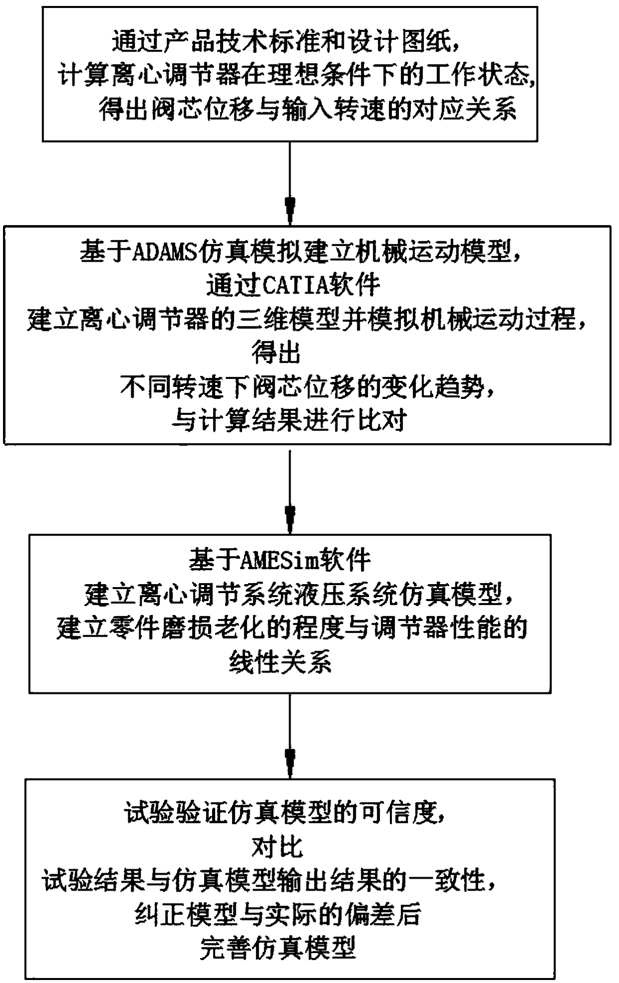
[0066] Such as figure 1 As shown, the repair tolerance analysis method based on the calculation and simulation of the constant speed transmission adjustment system includes:

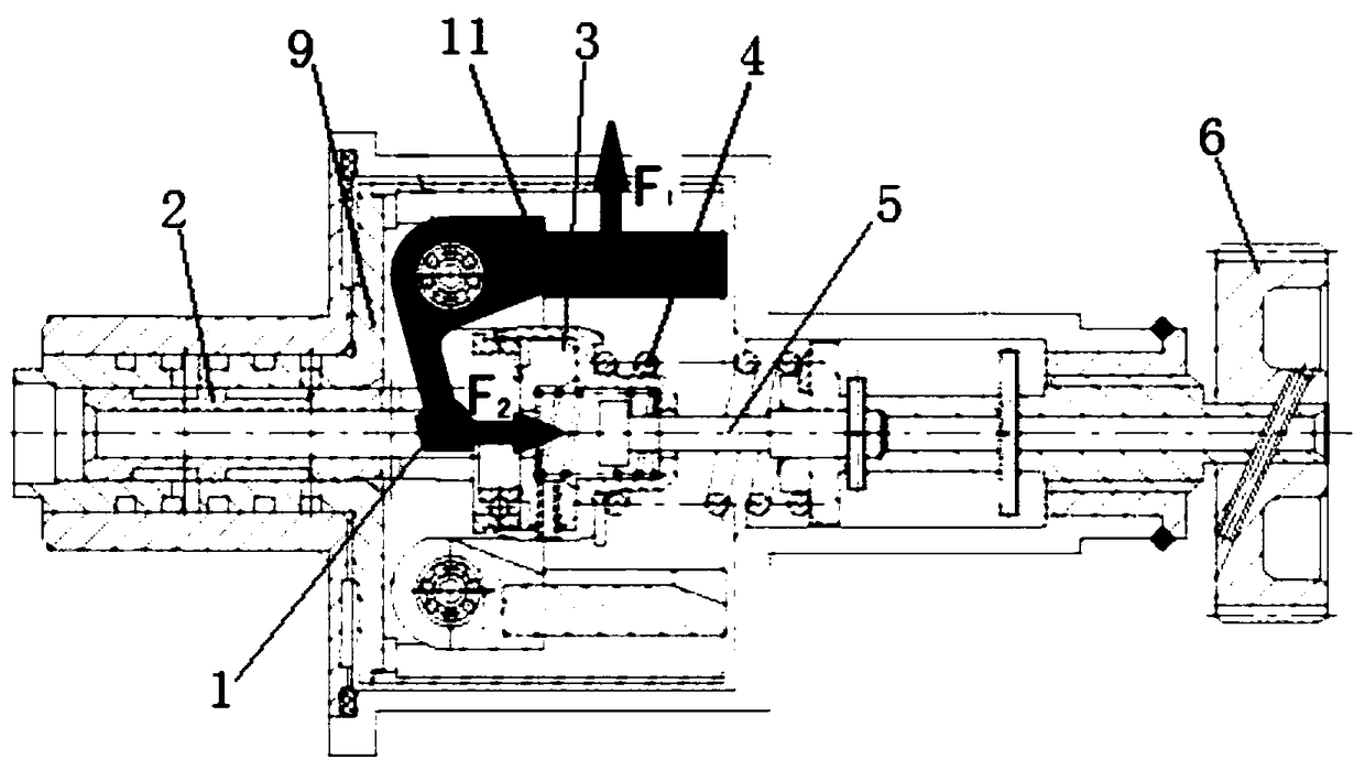
[0067] Step 1: Calculate the working state of the centrifugal regulator under ideal conditions through product technical standards and design drawings, and obtain the corresponding relationship between the displacement of the valve core 2 and the input speed;

[0068] Among them, the calculation of the working state of the centrifugal regulator under ideal conditions includes the following parameters;

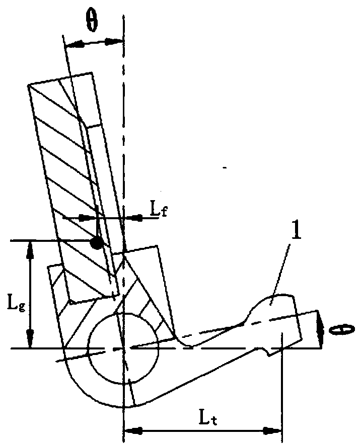
[0069] 11) Component parameters of the centrifugal block 11, the relationship between the distance from the contact position of the claw 1 on the centrifugal block seat and the valve core 2 to the rotating shaft, ...


PUM


Abstract

The invention relates to a repairing tolerance analysis method based on the calculation and simulation of a constant speed transmission device regulating system, which comprises the following steps: firstly, calculating the working state of a centrifugal regulator under an ideal condition through a product technical standard and a design drawing, and obtaining a corresponding relationship betweena valve core displacement and an input rotational speed; Secondly, based on ADAMS simulation, the mechanical motion model is established, and the three-dimensional model of the centrifugal regulator is established to simulate the mechanical motion process, and the change trend of the valve spool displacement at different rotational speeds is obtained, which is compared with the calculated results.thirdly, establishling a simulation model of that hydraulic system of the centrifugal regulating system, and establish a linear relationship between the wear and aging degree of the parts and the performance of the regulator; Fourthly, the credibility of the simulation model is verified by experiments, and the simulation model is perfected after the deviation between the model and the reality iscorrected. Fifthly, Determining Repair Tolerance. The invention can provide the technical support for the repair of the constant speed transmission device through the calculation and simulation analysis of the centrifugal regulator and the determination of the repair tolerance.

Description

technical field [0001] The invention relates to the technical field of aviation constant-speed transmission devices, in particular to a repair tolerance analysis method based on calculation and simulation of the adjustment system of the constant-speed transmission device. Background technique [0002] As we all know, the constant speed transmission device is an important part in the aircraft power system, which is used to convert the variable speed output by the engine into a constant speed for the alternator to generate alternating current with a stable frequency. After the constant speed transmission device works for a long time, the movement of the parts will cause wear, fatigue, deformation and other phenomena, resulting in deviations in the performance of the speed compensation system. Due to the complex structure of the constant speed transmission device, there are many factors that affect the normal operation of the system. Conventional maintenance methods can only be ...

Claims


Application Information

Patent Timeline
IPC IPC(8): G06F17/50
CPCG06F30/17G06F30/20
Inventor 王悦罗雁彭杰张铮蔡沛军
Owner WUHU SHUANGYI AERO TECH
Learn More