Supercharge Your Innovation With Domain-Expert AI Agents!

Reflowable Thermal Cutoffs

A thermal fuse, welding technology, applied in the direction of protection switch operation/release mechanism, electrical components, thermal switches, etc., can solve the problems of complex structure of reflowable thermal fuse, achieve simplified structure, avoid tension reduction, accurate fixed or maintained effect

Active Publication Date: 2021-03-30
POLYTRONICS TECH
View PDF10 Cites 0 Cited by
  • Summary
  • Abstract
  • Description
  • Claims
  • Application Information

AI Technical Summary

Problems solved by technology

However, the structure of the reflowable thermal fuse 10 is complicated, wherein the inhibiting element 13 and the sensing element 12 are actuated by different mechanisms.

Method used


Image

  • Reflowable Thermal Cutoffs
  • Reflowable Thermal Cutoffs
  • Reflowable Thermal Cutoffs

Examples


Embodiment Construction

[0063] In order to make the above and other technical content, features and advantages of the present invention more comprehensible, the following specifically cites relevant embodiments, together with the accompanying drawings, for a detailed description as follows.

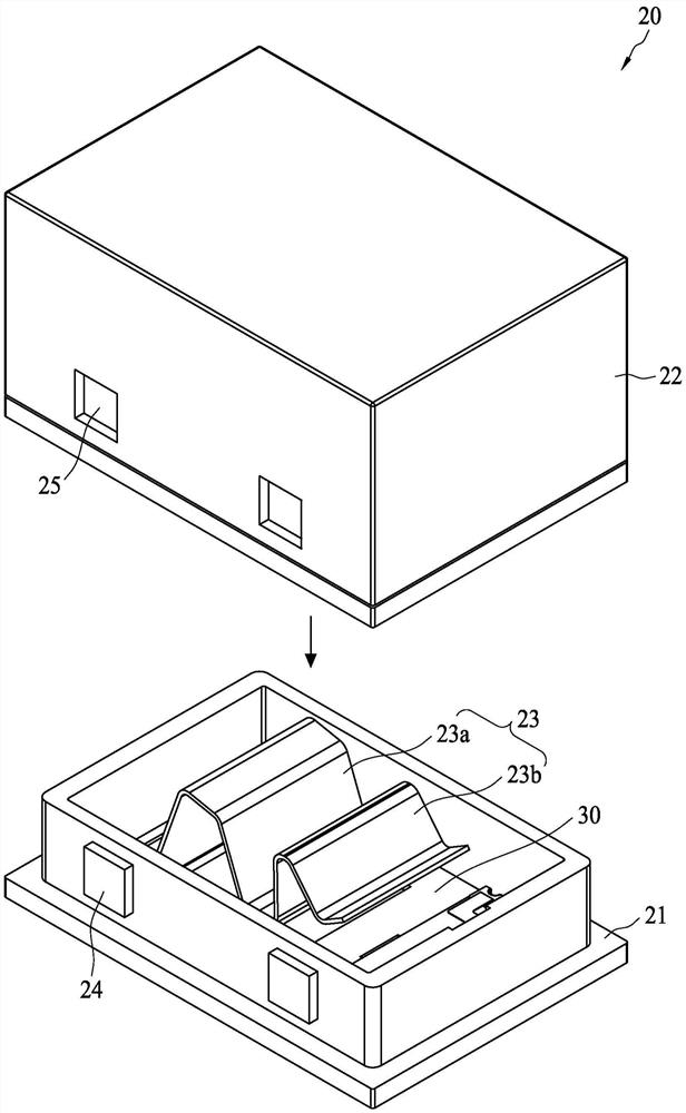
[0064] figure 2 A reflowable thermal fuse 20 according to an embodiment of the present invention is shown in an actuated state. The base 21 cooperates with the cover 22 to form an inner space capable of accommodating necessary components of the reflowable thermal fuse 20 . The conductive member 23 is disposed on the base 21 and includes a first elastic portion 23 a and a second elastic portion 23 b. The side wall of the base 21 is provided with a protruding block 24, and the protruding block 24 can engage with the notch 25 of the side wall of the housing 22, so as to combine the two. The conductive member 23 can be bent from a single metal sheet to form two arched portions, which respectively correspond to th...


PUM


Abstract

The present invention discloses a reflow thermal fuse. The reflow thermal fuse comprises a conductive part, a sensing part, an inhibition part, a heating part and a plurality of installation pads, andthe conductive part comprises a first elastic portion and a second elastic portion. The first elastic portion applies force to the conductive part when the reflow thermal fuse is in an actuation state. The sensing part is in mechanical connection with the first elastic portion. The inhibition part is configured to fix the second elastic portion when the reflow thermal fuse is in an installation state to prevent the second elastic portion from applying force to the conductive part. The heating part heats through an actuation current and transmits the heat to the inhibition part to allow the inhibition part to lose the elastic force and release the second elastic portion so as to allow the reflow thermal fuse to be in the actuation state. When errors occur in the later stage, the sensing part loses the capacity for maintenance of the position of the first elastic portion to allow the conductive part to form an open circuit.

Description

technical field [0001] The invention relates to a thermal fuse, in particular to a reflowable thermal fuse. Background technique [0002] With the development of science and technology, electric / electronic products are increasingly diversified and complex, and the circuit protection components used are not limited to the simple glass tube fuses in the past, but have developed into a wide variety of emerging electronic components. With the upgrading of electronic products, the requirements for reliability and safety are increasing, especially people will pay more attention to the development and application of various circuit protection components. [0003] The importance of circuit protection components is increasing day by day. In various electronic products, there is an increasing tendency to install over-current protection and over-voltage protection components. According to statistics, more than 75% of the failures in electronic products are caused by overcurrent or ov...

Claims


Application Information

Patent Timeline
Patent Type & Authority Patents(China)
IPC IPC(8): H01H37/76H01H71/20
CPCH01H37/761H01H71/20H01H2037/763
Inventor 苏聪敏蔡东成王绍裘
Owner POLYTRONICS TECH
Features
  • R&D
  • Intellectual Property
  • Life Sciences
  • Materials
  • Tech Scout
  • Unparalleled Data Quality
  • Higher Quality Content
  • 60% Fewer Hallucinations
Learn More