Bus duct with dust removal device

A technology of dust removal device and busway, which is applied in the field of busway, can solve the problems of affecting the heat dissipation effect of busway, reducing the safety performance of busway, and not having heat dissipation performance, etc., so as to achieve good practicability, avoid excessive dust accumulation, and improve the degree of automation Effect

Inactive Publication Date: 2019-02-26
TIANYUAN HUAWEI GRP
View PDF3 Cites 3 Cited by
  • Summary
  • Abstract
  • Description
  • Claims
  • Application Information

AI Technical Summary

Problems solved by technology

However, there are also defects in the busway, especially in the heat dissipation performance of the busway. Since the cluster arrangement between the busway usually generates high heat, the heat dissipation of the busway has become an important factor for R&D personnel to consider when developing products.
Especially for medium and high voltage bus ducts, since such bus ducts are mainly medium and high voltage power trunk lines, the heat dissipation performance, safety performance and whether the power consumption can be effectively reduced are very important. If such high voltage bus ducts are not With the necessary heat dissipation performance, once the high temperature generated by the connecting conductive bar in the busway cannot be dissipated in time, it is likely to bring hidden dangers to fire safety
After the bus duct works for a long time, the dust in the air is easy to accumulate on the upper cover, which seriously affects the heat dissipation effect of the bus duct and reduces the safety performance of the bus duct

Method used


Image

  • Bus duct with dust removal device
  • Bus duct with dust removal device
  • Bus duct with dust removal device

Examples


Embodiment Construction

[0019] In order to make the content of the present invention more clearly understood, the present invention will be further described in detail below based on specific embodiments and in conjunction with the accompanying drawings.

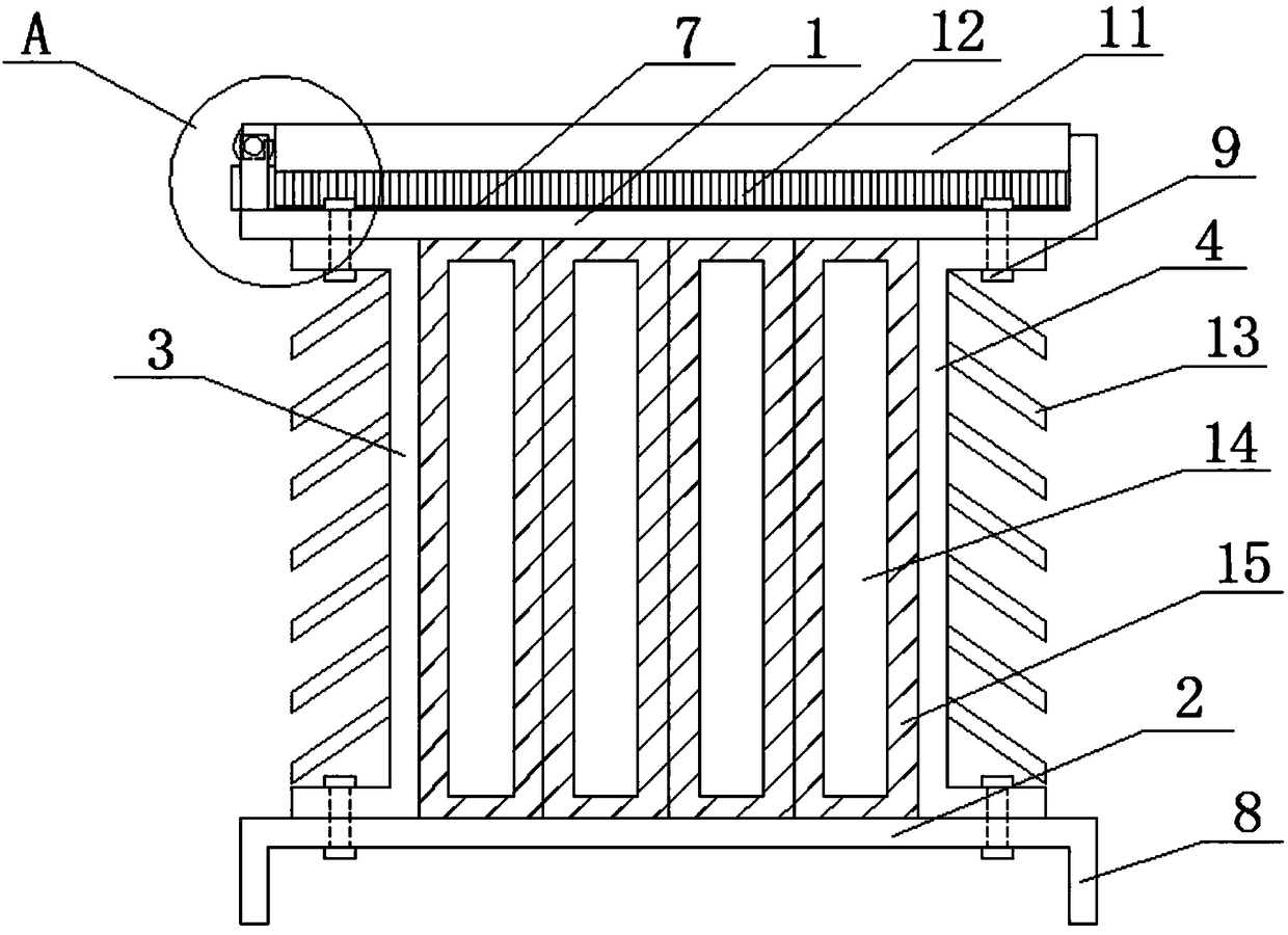
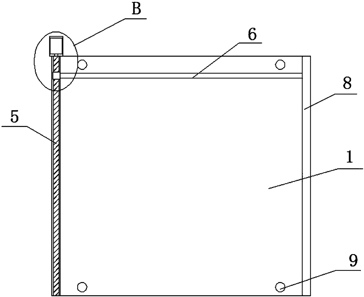
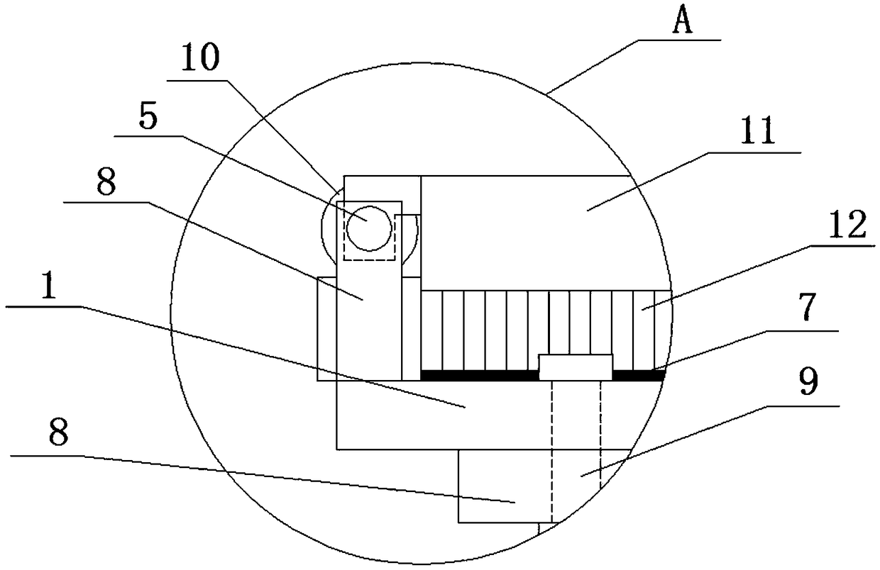
[0020] Such as Figure 1-5 As shown, a bus duct with a dust removal device includes a tank body, a dust removal device and a control device. The tank body includes an upper cover plate 1, a lower cover plate 2, a left side plate 3 and a right side plate 4, the The dust removal device includes a power mechanism, a ball screw 5 and a dust removal brush 6, the ball screw 5 is arranged on one side above the upper cover plate 1, the power mechanism is arranged at the end of the ball screw 5, and the dust removal brush 6 Set above the upper cover plate 4, the dust removal brush 6 is connected to the ball screw 5, the upper surface of the upper cover plate 1 is provided with a dust sensor 7, the output end of the dust sensor and the input end of the contr...


PUM


Abstract

The invention discloses a bus duct with a dust removing device, comprising a tank body, a dust removing device and a control device. The tank body comprises an upper cover plate, a lower cover plate,a left side plate and a right side plate, and the dust removing device comprises a power mechanism, a ball screw and a dust removing brush. The ball screw is arranged on one side on the upper cover, the power mechanism is arranged at an end of the ball screw, and the dust removing brush is arranged on the upper cover. The dust removing brush is connected to the ball screw, the upper surface of theupper cover is provided with a dust sensor, the output end of the dust sensor is connected to the input end of the control device, the output end of the control device and the input end of the powermechanism are connected, and the output end of the power structure is connected to the ball screw. According to invention, the dust sensor is used to detect the ash accumulation conditions on the upper cover in real time, and by controlling the dust removal device to clean the accumulated ash through the controller, the heat dissipation effects and safety performance of the bus duct are improved,and the damage rate of the bus duct is reduced.

Description

technical field [0001] The invention relates to a bus duct with a dust removal device, which is suitable for the field of electric power transmission. Background technique [0002] With the rapid development of the city, the power load of buildings increases with the increase of high-rise buildings, the traditional power transmission equipment gradually cannot meet the needs of the market, and the busway gradually replaces the position of wires and cables in the market. In recent years, busway has become the mainstream in power transmission lines. For example, in important projects such as hotels, airports, and subways, busway accounts for a large part. Therefore, the safety and stability of busway are very important. However, there are also defects in the busway, especially in the heat dissipation performance of the busway. Because the cluster arrangement between the busway usually generates high heat, the heat dissipation of the busway has become an important factor for R&...

Claims


Application Information

Patent Timeline
Patent Type & Authority Applications(China)
IPC IPC(8): H02G5/06H02G5/10B08B13/00B08B1/00
CPCB08B1/002B08B1/008B08B13/00H02G5/06H02G5/10
Inventor 孙延锋葛祥马琴
Owner TIANYUAN HUAWEI GRP
Why Eureka
Try Eureka