Permanent magnet brushless motor

A technology for permanent magnet brushless motors and motor casings, which is applied in the direction of electrical components, electromechanical devices, electric components, etc., and can solve the problems of permanent magnets and other components not working normally, damage to the internal circuit of the motor, and poor heat dissipation speed and effect. Achieve the effects of reducing rotor loss and aging, improving heat conduction speed and efficiency, high safety and heat dissipation efficiency

Pending Publication Date: 2019-02-26
吴世清
View PDF0 Cites 2 Cited by
  • Summary
  • Abstract
  • Description
  • Claims
  • Application Information

AI Technical Summary

Problems solved by technology

[0002] In today's electric tools, the motor is a commonly used driving device, and in some small devices, such as hand-held electric drills, etc., which require motors to provide high-speed rotation, small motors are the most important driving device, and forever The magnetic brushless motor is one of the most suitable motors for this type of equipment at present. Most of the existing motors of this type are designed through the open or semi-open design of the motor casing, that is, part of the motor body is exposed to the air. The design in this design, while reducing the weight of the equipment, it also convects the air inside the motor with the air outside the motor, speeds up heat dissipation, and improves heat dissipation efficiency. However, at the same time, it also brings some problems. On the one hand, the permanent The magnetic brushless motor itself is magnetic due to the use of permanent magnets and other components. It is very easy to absorb metal dust in the working environment into the motor and accumulate inside the motor, which affects the heat dissipation of the motor and causes machine failures such as circuit short circuits. Serious It may even happen that the dust accumulated in the motor for a long time will be adsorbed into blocks, damaging the internal circuit of the motor, making the permanent magnet and other components unable to work normally, and what is more serious is that some flammable and explosive dust will burn under certain conditions after entering the motor. A serious explosion accident will occur after contact with the ignition source, which is extremely unsafe for the user. On the other hand, due to the special working environment and in order to reduce the volume of the equipment, usually do not install a fan and rely on the motor itself to directly dissipate heat The heat dissipation after the operation of the equipment is carried out in the form of equipment, and the heat dissipation speed and effect are often poor

Method used


Image

  • Permanent magnet brushless motor
  • Permanent magnet brushless motor
  • Permanent magnet brushless motor

Examples


Embodiment Construction

[0014] In order to make the technical means, innovative features and functions realized by the present invention easy to understand, the present invention will be further described below.

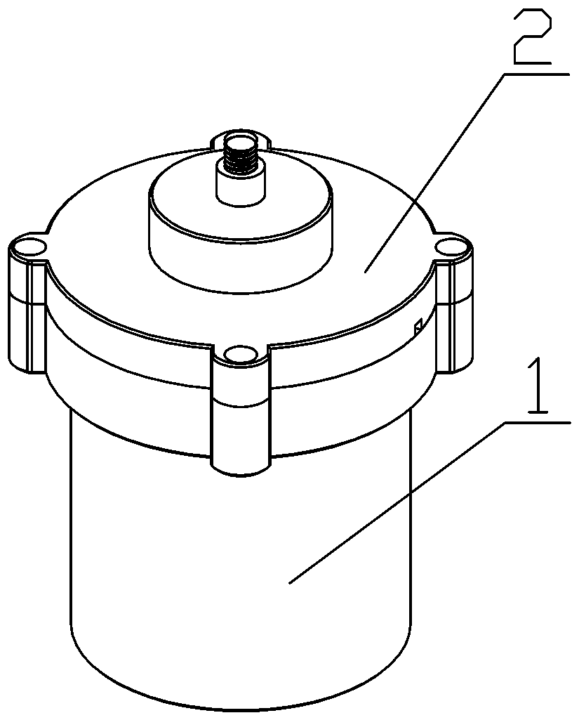
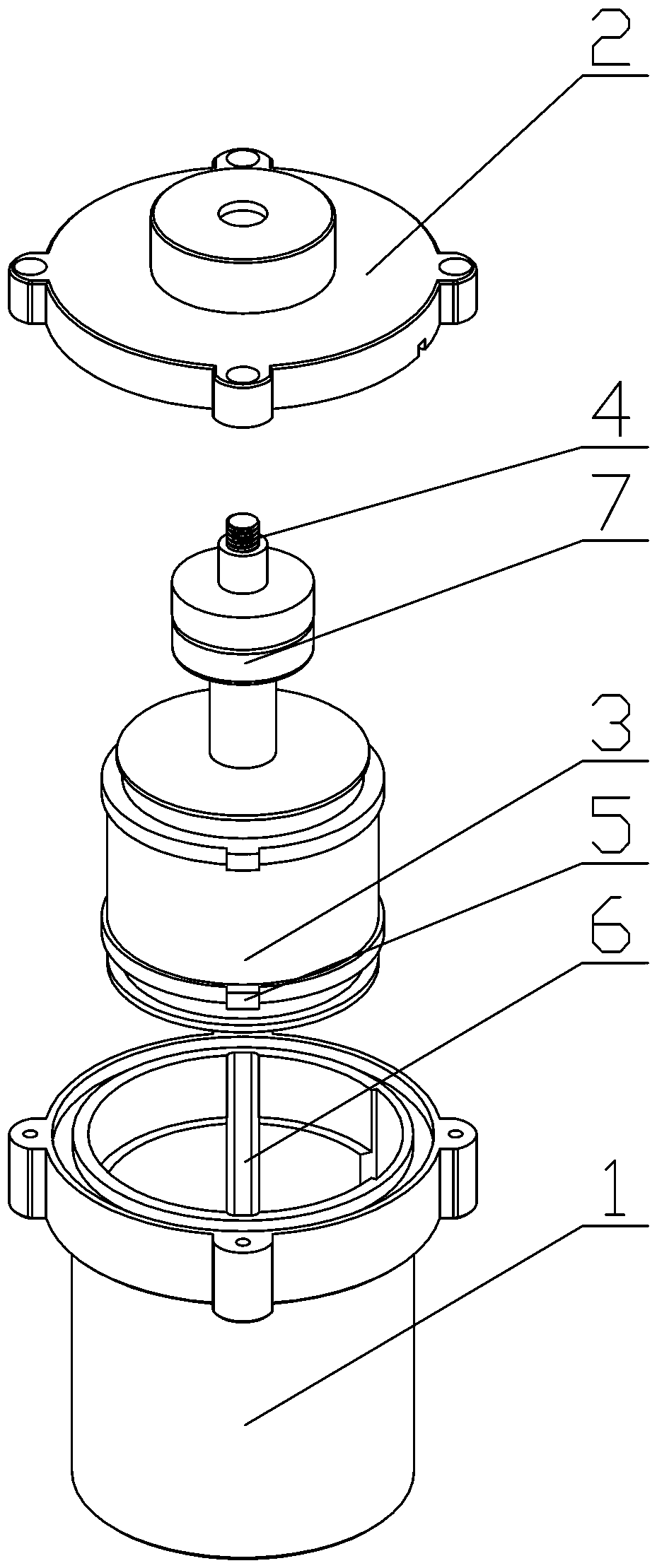
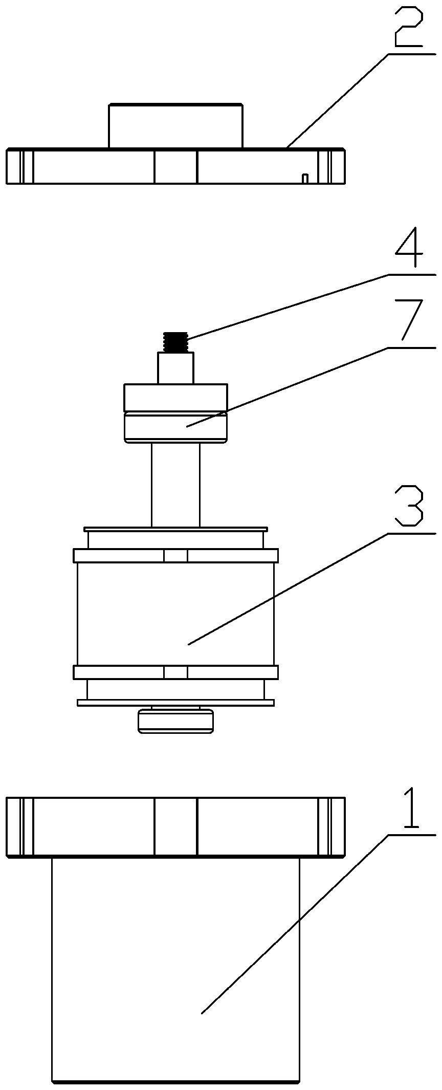
[0015] like figure 1 , figure 2 and image 3 As shown, an embodiment of the permanent magnet brushless motor of the present invention includes a motor casing 1 with a cavity, a motor upper cover 2 with a sealing cover connected to the top of the motor casing 1, a motor stator 3, a rotor shaft, and a motor shaft driven by the rotor shaft. The motor rotor 4, the motor body composed of the motor stator 3, the motor rotor 4 and the rotor shaft is fixedly installed in the cavity of the motor housing 1, the center of the motor upper cover 2 has a shaft hole, and the rotor shaft passes through The upper cover of the motor has 2 shaft holes and is connected with the upper cover of the motor 2 in a relatively rotating and sealed manner. The cavity is filled with insulating thermal fluid. When the...


PUM


Abstract

A permanent magnet brushless motor comprises a motor casing with a cavity, a motor upper cover with a sealing cover connected over the motor casing, a motor stator, a rotor shaft and a motor rotor driven by the rotor shaft. A motor body constituted by the motor stator, the motor rotor and the rotor shaft is fixedly mounted in the cavity of the motor casing. The motor upper cover has a shaft hole at the center thereof. The rotor shaft passes through the shaft hole of the motor upper cover and is sealingly connected with the motor upper cover in a relatively rotating manner. The cavity is filledwith an insulating heat conducting fluid. When the motor is running, the heat generated by the rotor is conducted to the motor casing or/and the inner wall of the motor upper cover by the heat conducting fluid. The design has the advantages of high heat dissipation efficiency, safety and reliability, and long service life.

Description

technical field [0001] The invention relates to a permanent magnet brushless motor, in particular to a fully enclosed permanent magnet brushless motor applied to small electric tools. Background technique [0002] In today's electric tools, the motor is a commonly used driving device, and in some small devices, such as hand-held electric drills, etc., which require motors to provide high-speed rotation, small motors are the most important driving device, and forever The magnetic brushless motor is one of the most suitable motors for this type of equipment at present. Most of the existing motors of this type are designed through the open or semi-open design of the motor casing, that is, part of the motor body is exposed to the air. The design in this design, while reducing the weight of the equipment, it also convects the air inside the motor with the air outside the motor, speeds up heat dissipation, and improves heat dissipation efficiency. However, at the same time, it als...

Claims


Application Information

Patent Timeline
Patent Type & Authority Applications(China)
IPC IPC(8): H02K5/10H02K5/136H02K9/19H02K5/24
CPCH02K5/10H02K5/136H02K5/24H02K9/19
Inventor 吴世清
Owner 吴世清
Why Eureka
Try Eureka