
Automatic fire extinguishing device with leakage stopping structure

A technology of automatic fire extinguishing and fire extinguishing agent, which is applied in the fields of automatic fire extinguishing devices, fire prevention, suppression or extinguishing equipment, can solve the problems affecting the effect, and achieve the effect of simple structure, simple and convenient assembly, and strong safety

Inactive Publication Date: 2019-03-01
沈奂
View PDF6 Cites 2 Cited by
  • Summary
  • Abstract
  • Description
  • Claims
  • Application Information

AI Technical Summary

Problems solved by technology

The automatic fire extinguisher is placed where it needs to be placed. When a fire breaks out at the place where it is placed, the lower part of the thermal activation line 40' will be ignited immediately, and the entire thermal activation line 40' will undergo a combustion reaction, making the first cavity 11' located in the base 10' The gas generating agent undergoes oxidation-reduction reaction to generate a large amount of inert gas, and the generated inert gas breaks through the film sealed in the second through hole 31' of the diffuser cover 30', and is sprayed from the second through hole 31' of the diffuser cover. out, into the second chamber 21' containing the fire extinguishing agent of the bottle body 20', as a driving force to make the fire extinguishing agent in the second chamber 21' of the bottle body 20' spray out from the nozzle 50' of the automatic fire extinguisher, In order to achieve the purpose of extinguishing the fire; this kind of structure, after the heat starting line 40' of the base 10' burns, the first through hole 12' of the base 10' is connected with the outer space of the base 10' at this time, and the inside of the bottle body 20' The gas pressure will be released from the first through hole 12' of the base 10', such as Figure 9 As shown by the middle arrow B, the internal air pressure flows out from the direction indicated by the arrow B to release the pressure, so that the pressure in the bottle body 20' becomes smaller, and the spraying force will be weakened, thus affecting the effect of fire extinguishing

Method used


Image

  • Automatic fire extinguishing device with leakage stopping structure
  • Automatic fire extinguishing device with leakage stopping structure
  • Automatic fire extinguishing device with leakage stopping structure

Examples


Embodiment Construction

[0024] The present invention will be described in further detail below in conjunction with each accompanying drawing.

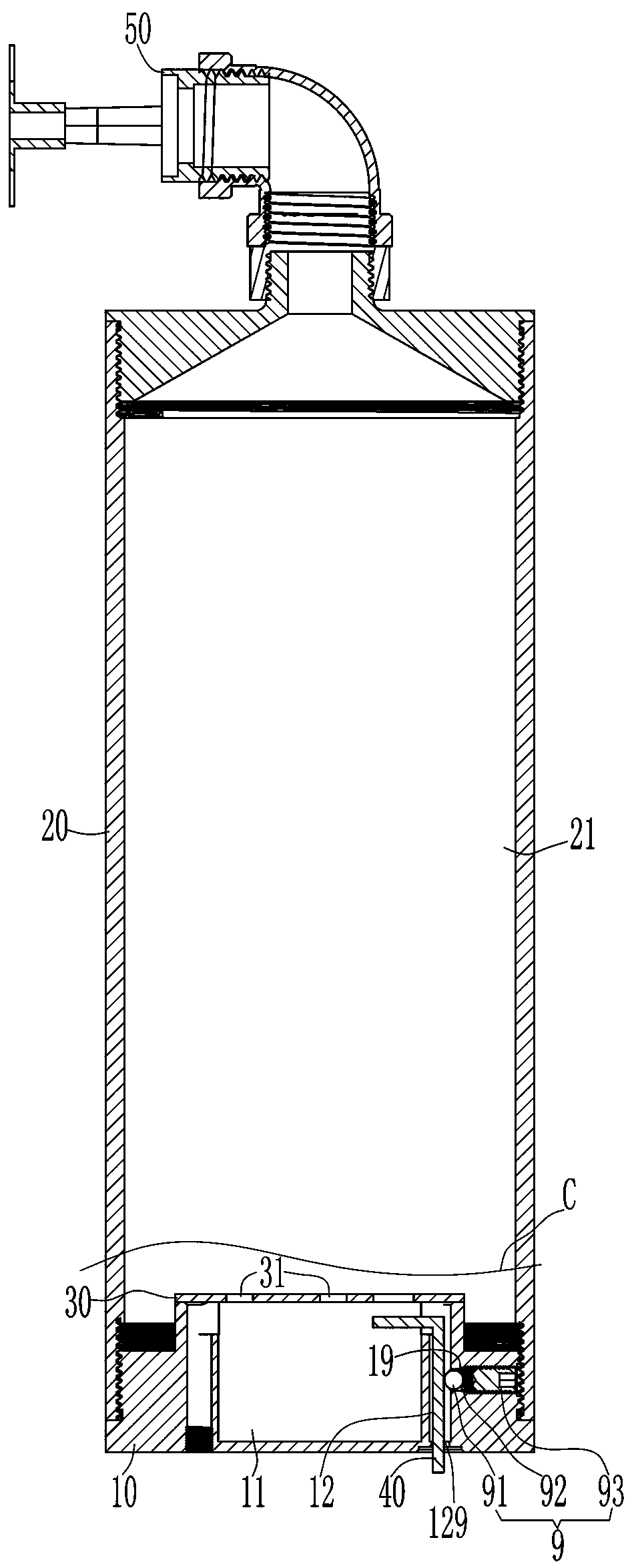
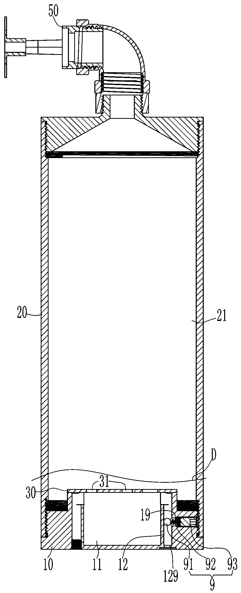
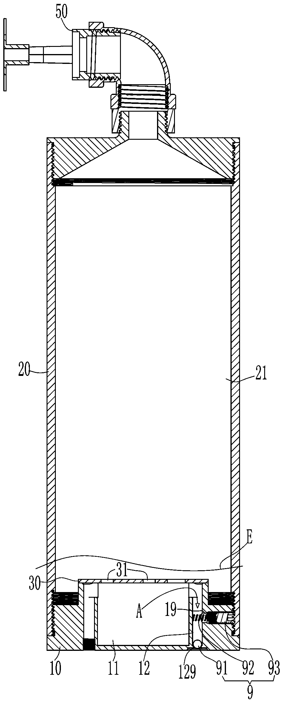
[0025] see Figure 1 to Figure 7, an automatic fire extinguishing device provided with an anti-leakage structure, comprising a base 10, a bottle body 20, a gas diffuser cover 30 and a thermal activation wire 40; the base 10 is provided with a first cavity 11 for accommodating a gas generating agent and a The first cavity 11 communicates with the first through hole 12, and the first through hole 12 also communicates with the outer space of the base 10, the first through hole 12 is actually set upward from the bottom of the base 10 A vertical through hole, after the thermal starting line 40 passes through the first through hole 12 of the base 10, one end is located in the first cavity 11 of the base 10, and the other end is exposed behind the bottom surface of the base 10 Located at the outer space of the base 10; the diffuser cover 30 is provided with at leas...


PUM


Abstract

The invention relates to an automatic fire extinguishing device with a leakage stopping structure. The automatic fire extinguishing device comprises a base, a bottle body with a second accommodating cavity, a gas dispersing cover with at least one second through hole, a thermal enable line and the leakage stopping structure, wherein a first accommodating cavity and a first through hole are formedin the base, the thermal enable line penetrates through the first through hole of the base, then, one end of the thermal enable line is located in the first accommodating cavity of the base, and the other end of the thermal enable line is located in an external space of the base; the second through holes of the gas dispersing cover are sealed up by a film, a gas generant is arranged in the first accommodating cavity of the base, and then, an opening of the first accommodating cavity is sealed up by the gas dispersing cover; the base is arranged at the lower end of the bottle body; when the thermal enable line is burnt, the leakage stopping structure can automatically block up the first through hole of the base, and thus, pneumatic pressure in the base and the bottle body cannot leak from the first through hole of the base. According to the automatic fire extinguishing device disclosed by the invention, no leakage of pneumatic pressure in the bottle body is guaranteed, the pressure in the bottle body can be sufficient, and the jet effect of a fire extinguishing agent in the bottle body can be optimal; the automatic fire extinguishing device has the advantages of simple and practicalstructure, simplicity and convenience in assembly, high safety, and the like.

Description

【Technical field】 [0001] The present invention relates to fire-fighting equipment, in particular to equipment suitable for fire prevention, suppression or extinguishment, especially to an automatic fire extinguishing device. 【Background technique】 [0002] With the development of the economy and the progress of the society, more and more fire extinguishers (also known as fire extinguishing devices) have entered each of our families, kitchens, indoors and outdoors, and can be used from any angle; fire safety has become an inevitable social consensus. All kinds of fire-fighting equipment are more and more developed in the direction of energy saving, environmental protection, convenient use, safety and high efficiency. Fire extinguishers have become an important part of people's life and property safety. [0003] see Figure 8 and Figure 9 , There is an automatic fire extinguisher in the prior art, which includes a base 10', a bottle body 20', a gas diffuser cover 30' and a ...

Claims


Application Information

Patent Timeline
Patent Type & Authority Applications(China)
IPC IPC(8): A62C31/00A62C31/28A62C37/00
CPCA62C31/005A62C31/28A62C37/00
Inventor 沈奂
Owner 沈奂
Learn More