Flushing device with porous rotary jet structure

A technology of flushing device and jet, applied in the directions of cleaning hollow objects, cleaning methods and utensils, chemical instruments and methods, etc., can solve the problems of insufficient water power, no mention, damage, etc. Loss, increased speed and pressure, effect of increased cleaning efficiency

Active Publication Date: 2021-02-12
CHINA UNIV OF PETROLEUM (EAST CHINA)
View PDF19 Cites 6 Cited by
  • Summary
  • Abstract
  • Description
  • Claims
  • Application Information

AI Technical Summary

Problems solved by technology

The hydraulic source of the water jet is often obtained locally, using the water in the lotus pond. In the process of designing the jet circuit, it will inevitably involve the problems of jet water suction, drainage, and filtration. Even if the jet water filtration system is designed and installed, it will With the increase of use time, weeds, straw and other sundries in the pond will inevitably block the water absorption hole of the water absorption sleeve of the lotus root harvester, resulting in insufficient water power of the lotus root harvester, and the suction pump will run idly, causing damage
After investigation, it is found that there is no mention of any device on the market, as well as in numerous documents and patents, that involves flushing the suction holes on the suction sleeve of the lotus root harvester

Method used


Image

  • Flushing device with porous rotary jet structure
  • Flushing device with porous rotary jet structure
  • Flushing device with porous rotary jet structure

Examples


Embodiment 1

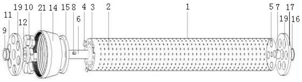
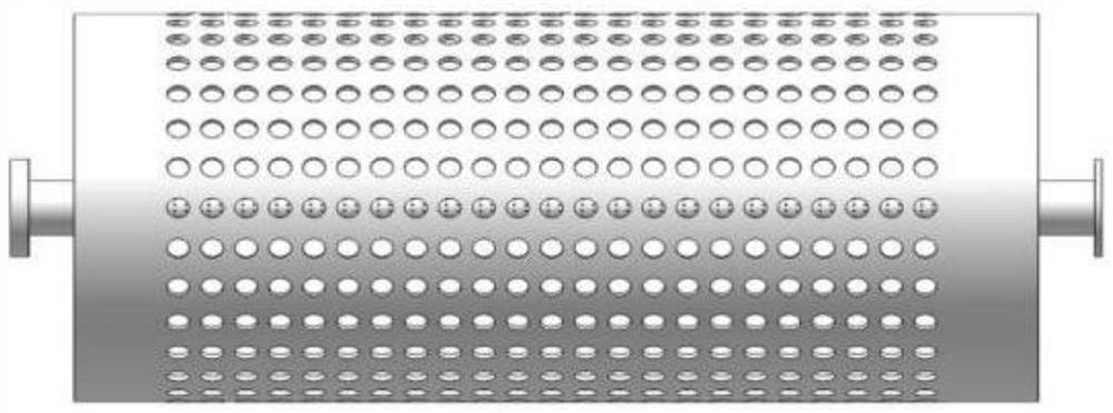
[0020]The main structure of the flushing device with a porous rotating jet structure involved in this embodiment includes a rotating water jet shaft barrel 1, a water jet hole 2, a water inlet hole 3, a buckle 4, a water outlet hole 5, a front shaft 6, a rear shaft 7, and a spline 8 , No. 1 bearing bush 9, turbofan 10, front splitter 11, keyway 12, front flange 13, drainage pipe 14, sealing ring 15, No. 2 bearing bush 16, rear splitter 17, rear flange 18 , diversion holes 19 and positioning protrusions 20; the outer circumference of the hollow cylindrical structure of the rotary water jet shaft tube 1 is uniformly provided with several circular water jet holes 2, and the left end surface of the rotary water jet shaft tube 1 Several water inlet holes 3 of circular structure and buckles 4 of wedge-shaped structure are arranged at equal intervals, and several water outlet holes 5 of circular structure are arranged at equal intervals on the right end surface of the rotating water j...

Embodiment 2

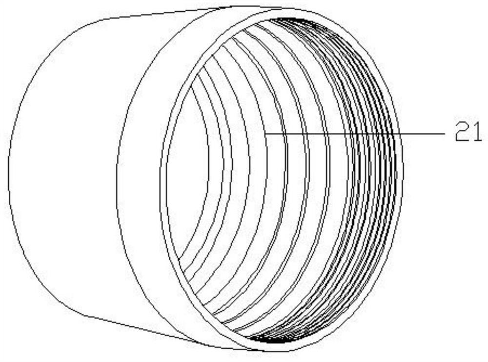
[0022] When the flushing device with porous rotating jet structure involved in this embodiment is prepared and used, the front flange 13 and the rear flange 18 are respectively connected with the water-absorbing sleeve 100 bolted on the lotus root harvester, and the water flows from the front The blue plate 13 enters, passes through the split hole 19 of the front splitter 11, and acts vertically on the blade of the turbofan 10. Since the front splitter 11 is fastened in the front flange 13, the front splitter 11 is affected by the impact of the water flow. The bottom will not move to the right, the turbofan 10 rotates under the impact of the water flow, and at the same time drives the rotating water jet shaft barrel 1 to rotate; The bionic earthworm body surface pattern 21 on the inner wall can reduce the pressure loss along the water flow. The buckle 4 of the wedge structure and the sealing ring 15 of the ring structure work together to ensure the sealing of the waterway and e...


PUM


Abstract

The invention belongs to the technical field of flushing preparation, and particularly relates to a flushing device with a porous rotary jet structure. A rotary water jet shaft cylinder is adopted forjet cleaning, and large-area and small-caliber jet holes are formed in the rotary water jet shaft cylinder, so that the water jet coverage area is ensured; and the rotary water jet shaft cylinder canbe driven by a turbine turbofan to rotate 360 degrees, so that the cleaning efficiency is greatly improved. By adopting a bionics principle, lines with the same appearance characteristics as earthworm skin are arranged on the inner wall of a drainage pipe and are used for reducing the on-way pressure loss of water flow and ensuring the pressure of a hydraulic head entering the rotary water jet shaft cylinder. Flow dividing holes have inclination angles, so that a water source flowing through the flow dividing holes can act on the fan surface of the turbine turbofan with the maximum area, andthe turbine turbofan is ensured to have enough power. A buckle with a wedge-shaped structure and a sealing ring are tightly matched with the drainage pipe with a conical structure, so that the contactresistance between the rotary water jet shaft cylinder and the drainage pipe is reduced, and meanwhile, the airtightness of a water jet loop is guaranteed.

Description

Technical field: [0001] The invention belongs to the technical field of flushing preparation, and in particular relates to a flushing device with a porous rotating jet structure, which can flush porous equipment, and in particular can quickly and efficiently flush the water absorption holes on the water absorption sleeve of a lotus root harvester. Background technique: [0002] A high-speed water jet shot from a small-diameter hole acts on the material, using its energy to clean, peel, and cut the material. This property of the liquid has inspired researchers to develop new ways of "working with water" , turning the kinetic energy of the water jet into mechanical energy for material removal. [0003] The water jet is a high-speed water stream of different shapes formed by the nozzle, and the flow rate of the jet depends on the pressure drop before and after the nozzle outlet section. Water jetting is the simplest form of energy transformation and application. Usually, the ...

Claims


Application Information

Patent Timeline
Patent Type & Authority Applications(China)
IPC IPC(8): B08B9/032
CPCB08B9/0321
Inventor 蒋圣群刘衍聪岳吉祥程鸣冯岩
Owner CHINA UNIV OF PETROLEUM (EAST CHINA)
Why Eureka
Try Eureka