Heterogeneous metal material pipeline welding device

A technology of dissimilar metals and welding devices, applied in welding equipment, metal processing equipment, high-frequency current welding equipment, etc., can solve the problems of expensive and complicated equipment, poor welding effect, etc., and achieve improved welding quality and faster heating rate , the effect of easy assembly

Active Publication Date: 2019-03-01
UNIV OF SHANGHAI FOR SCI & TECH
View PDF12 Cites 2 Cited by
  • Summary
  • Abstract
  • Description
  • Claims
  • Application Information

AI Technical Summary

Problems solved by technology

[0002] At present, although resistance welding has been widely used in the industry, there are still some problems. Resistance welding of thin plate components with a thickness of less than 3mm requires expensive and complicated equipment, and the required current can be as high as 10kA. The contact requirements for welding are relatively large. High, resistance welding is not suitable for welding large-diameter metal pipes, the welding quality of resistance welding is controlled by many factors, and it is difficult to improve welding quality
The existing welding device is not very suitable for welding large-diameter dissimilar metal material pipes. Even if it can be welded, the welding effect is not good. And welding devices for medium and large diameter dissimilar metal material pipelines

Method used


Image

  • Heterogeneous metal material pipeline welding device
  • Heterogeneous metal material pipeline welding device
  • Heterogeneous metal material pipeline welding device

Examples


Embodiment 1

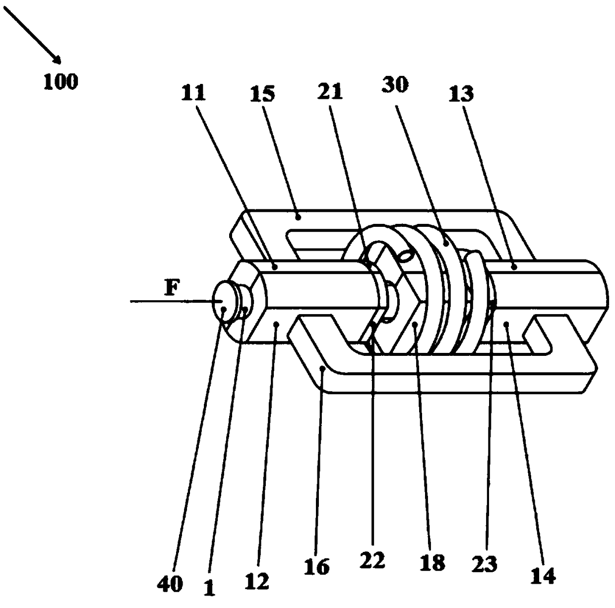
[0025] Such as Figure 1-Figure 4 As shown, a pipe welding device 100 of dissimilar metal materials in this embodiment is used for welding coaxial first pipe 1 and second pipe 2 of different metal materials, including: support sleeve assembly 10, heat insulation assembly 20 and high frequency induction heating coil 30.

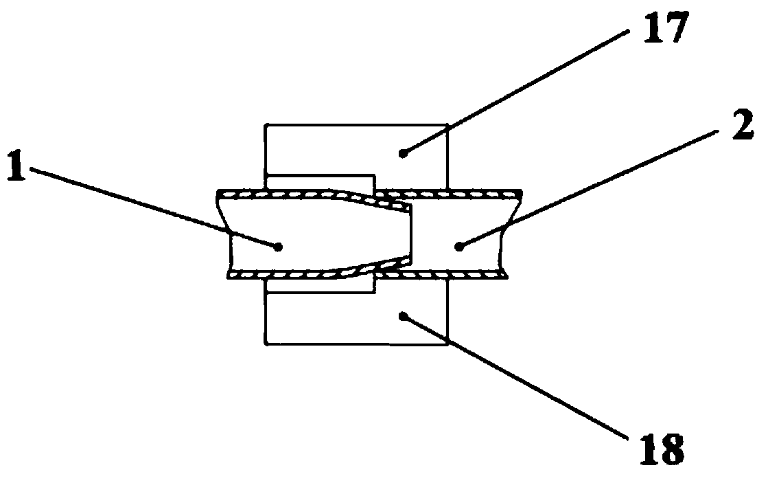
[0026] The first pipe 1 is a copper pipe with a tapered front end, the second pipe 2 is an aluminum pipe, and the tapered portion of the first pipe 1 is inserted into the second pipe 2 .

[0027] A hydraulic cylinder (not shown in the figure) is connected to the tail end of the first pipe 1 for applying pressure F to the first pipe 1 .

[0028] The first pipe 1 passes through the upper support sleeve 11 of the first pipe, the lower support sleeve 12 of the first pipe, and a baffle plate 40 for making the stress on the first pipe 1 more uniform is arranged between the hydraulic push rod of the hydraulic cylinder.

[0029] A stopper (not shown in the figure) i...

Embodiment 2

[0056] Such as Figure 5-Figure 6 As shown, this embodiment has a support sleeve assembly 10 , a heat insulation assembly 20 and a high-frequency induction heating coil 30 . Compared with Embodiment 1, the upper middle support sleeve 19 and the lower middle support sleeve 110 of this embodiment are different, having the following structure:

[0057] When the upper middle support sleeve 19 and the lower middle support sleeve 110 embrace the first pipe 1 and the second pipe 2 in the radial direction, there is a gap between the upper middle support sleeve 19 and the lower middle support sleeve 110 for discharging the copper-aluminum eutectic liquid .

[0058] Both the inner side of the upper middle support sleeve 19 and the inner side of the lower middle support sleeve 110 have a hole with the same radius as the outer radius of the first tube 1 at the coincidence place of the first tube 1 and the second tube 2 for discharging the eutectic liquid.

Embodiment 3

[0060] The structure of this embodiment is the same as that of Embodiment 1. There is a gap between the upper middle support sleeve 19 and the lower middle support sleeve 110 for discharging the copper-aluminum eutectic liquid, and the upper middle support sleeve 19 and the lower middle support sleeve respectively 110 is provided with grooves (not shown in the figure), two grooves are arranged on the left side of the junction of the first pipe 1 and the second pipe 2, and the groove on the upper middle support sleeve 19 is larger than that of the lower middle support sleeve 110 grooves are used to make the eutectic liquid flow out better when it flows upwards.


PUM

PropertyMeasurementUnit
thicknessaaaaaaaaaa

Abstract

The invention provides a heterogeneous metal material pipeline welding device which comprises a support sleeve assembly, a heat insulation assembly and a high frequency induction heating coil. The support sleeve assembly comprises a first pipe upper support sleeve and a first pipe lower support sleeve for positioning a first pipe, comprises a second pipe upper support sleeve and a second pipe lower support sleeve for positioning a second pipe, and comprises an upper support sleeve bracket with the two ends being fixed to the outer side of the first pipe upper support sleeve and the outer sideof the second pipe upper support sleeve, a lower support sleeve bracket with the two ends being fixed to the outer side of the first pipe lower support sleeve and the outer side of the second pipe lower support sleeve, and an upper middle support sleeve and a lower middle support sleeve, and the upper middle support sleeve and the lower middle support sleeve are arranged at the joint part of the first pipe and the second pipe; the heat insulation assembly comprises a first pipe upper heat insulation sheet arranged on the first pipe upper support sleeve, a first pipe lower heat insulation sheetarranged on the first pipe lower support sleeve, a second pipe upper heat insulation sheet arranged on the second pipe upper support sleeve, and a second pipe lower heat insulation sheet arranged onthe second pipe lower support sleeve; and the high frequency induction heating coil sleeves the outer sides of the upper middle support sleeve and the lower middle support sleeve.

Description

technical field [0001] The invention relates to a pipe welding device, in particular to a pipe welding device for dissimilar metal materials. Background technique [0002] At present, although resistance welding has been widely used in the industry, there are still some problems. Resistance welding of thin plate components with a thickness of less than 3mm requires expensive and complicated equipment, and the required current can be as high as 10kA. The contact requirements for welding are relatively large. High, resistance welding is not suitable for welding large-diameter metal pipes, the welding quality of resistance welding is controlled by many factors, and it is difficult to improve the welding quality. The existing welding device is not very suitable for welding large-diameter dissimilar metal material pipes. Even if it can be welded, the welding effect is not good. And welding devices for medium and large diameter pipes of dissimilar metal materials. Contents of t...

Claims


Application Information

Patent Timeline
Patent Type & Authority Applications(China)
IPC IPC(8): B23K13/02B23K101/06
CPCB23K13/025Y02P10/25
Inventor 曹蒙云张卓曹凯刘新宽王子延
Owner UNIV OF SHANGHAI FOR SCI & TECH
Why Eureka
Try Eureka