Mechanical maintenance rotating shaft polisher

A grinder and shaft technology, which is applied in the directions of grinding machines, grinding frames, grinding beds, etc., can solve the problems of low grinding efficiency, grinding interference of rotating shafts, easy arm soreness, etc., to improve grinding efficiency, reduce labor intensity, The effect of preventing arm soreness

Active Publication Date: 2019-03-01
浙江莱恩克风机有限公司
View PDF16 Cites 8 Cited by
  • Summary
  • Abstract
  • Description
  • Claims
  • Application Information

AI Technical Summary

Problems solved by technology

[0002] After the shaft is used for a period of time, rust will appear on the surface of the shaft, so it is necessary to polish the surface of the shaft. At present, when grinding the shaft, workers usually use a hand-held emery cloth to polish the shaft. It takes a long time to polish the shaft The arm is prone to soreness, and the grinding efficiency is low. In order to improve the grinding efficiency of the shaft, the workers will use a hand-held polishing machine to polish the shaft. However, when using the polishing machine to polish the shaft, sparks will be generated, which will interfere with the grinding of the shaft.

Method used


Image

  • Mechanical maintenance rotating shaft polisher
  • Mechanical maintenance rotating shaft polisher
  • Mechanical maintenance rotating shaft polisher

Examples


Embodiment 1

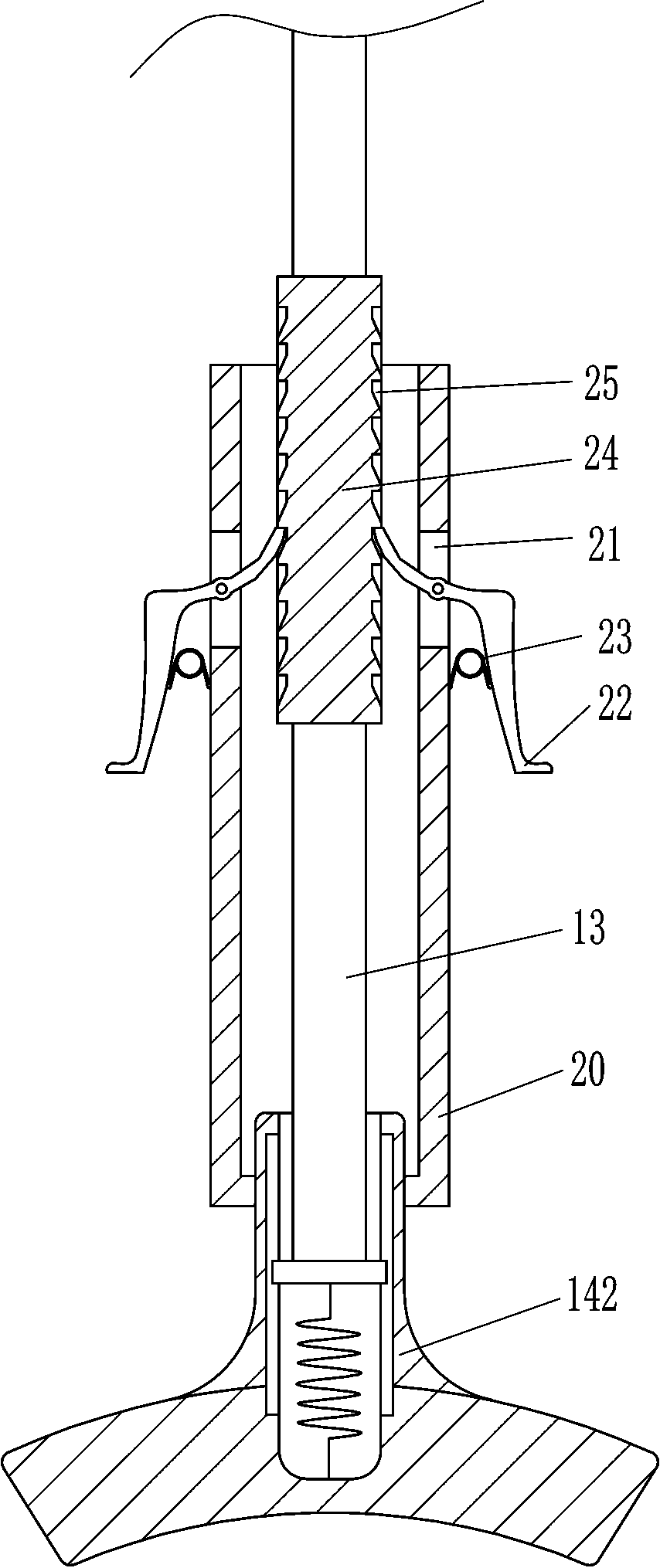
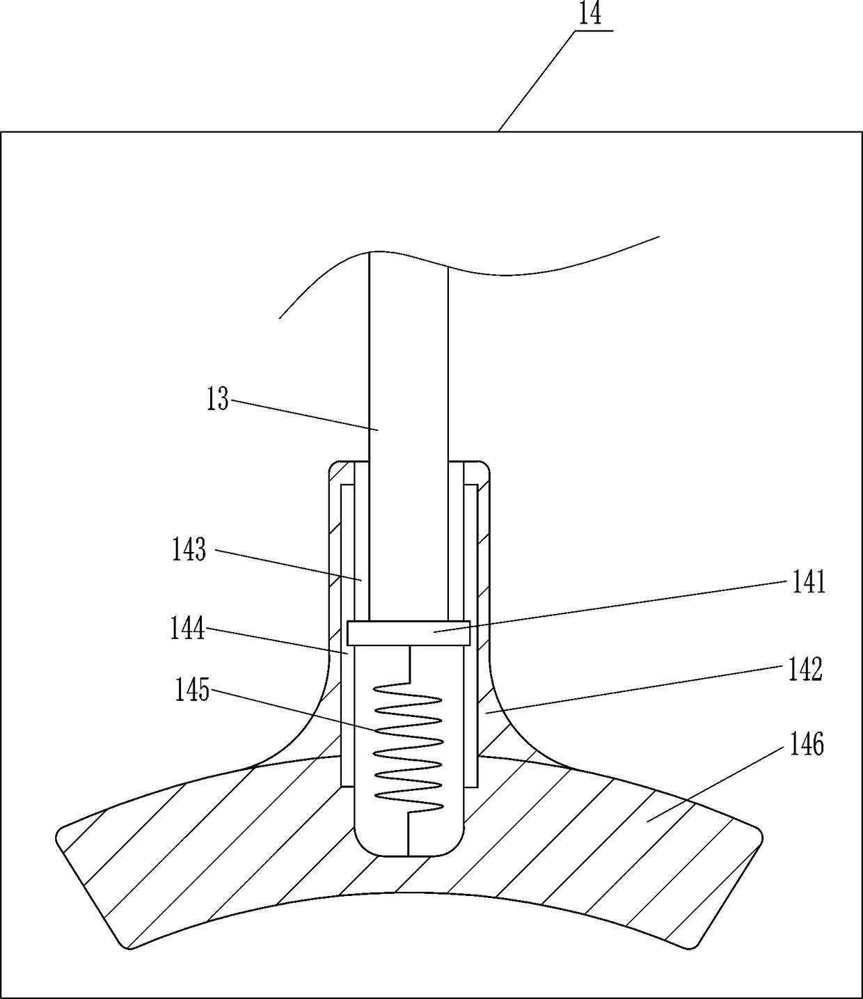
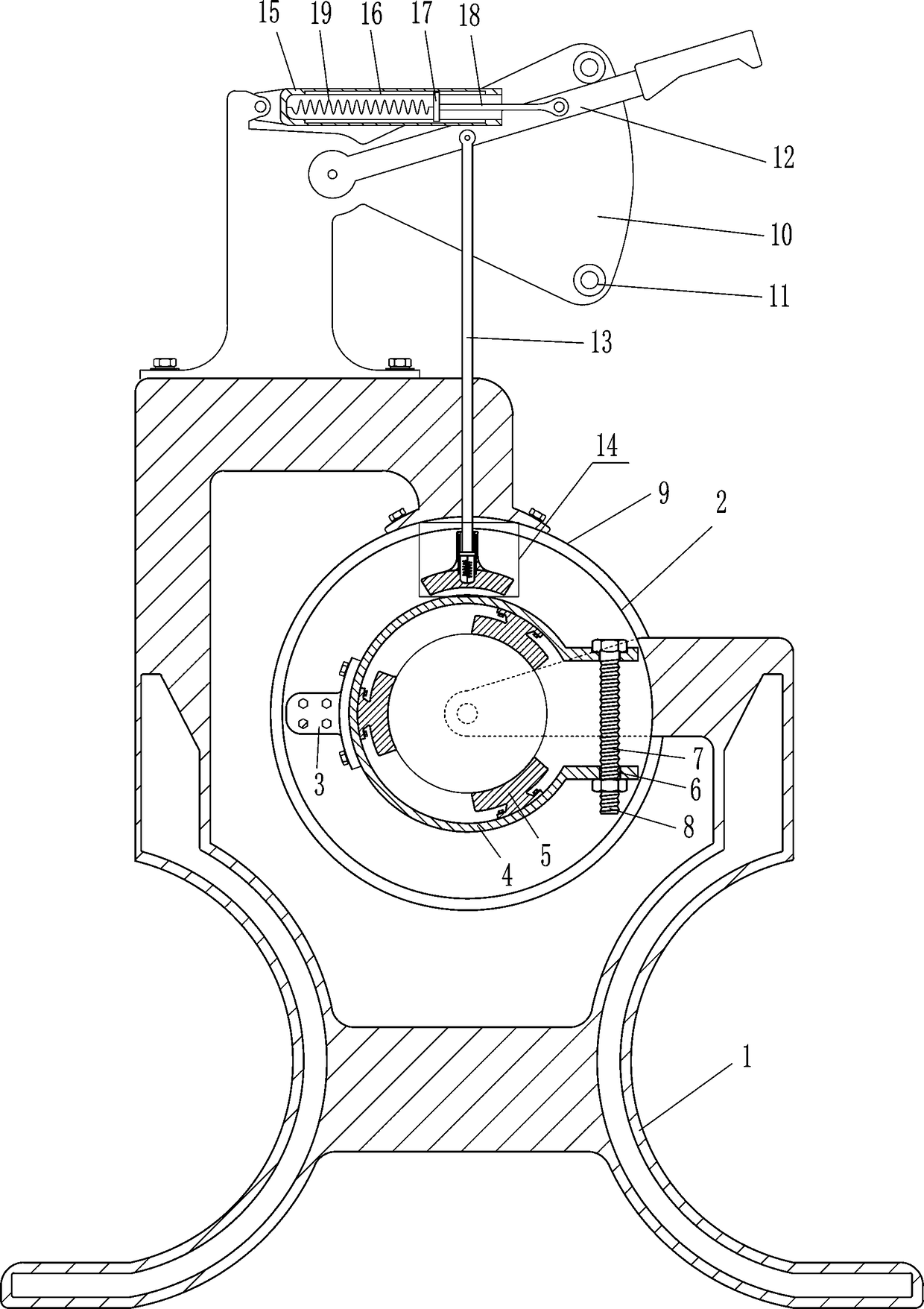
[0021] A mechanical maintenance shaft grinder, such as Figure 1-5 As shown, it includes a support 1, a turntable 2, a first fixed support plate 3, an elastic arc splint 4, a clamp block 5, a first screw rod 7, a nut 8, a motor 9, a second fixed support plate 10, and a fixed rod 11 , swing rod 12, first connecting rod 13, telescopic grinding device 14, first hollow tube 15, first slide rail 16, first slider 17, second connecting rod 18 and first spring 19, motor 9 is installed on the support In the middle of the upper part of the seat 1, the output shaft of the motor 9 passes through the support 1 and is fixedly connected with the turntable 2, the first fixed support plate 3 is installed on the left side of the front side of the turntable 2, and the elastic arc splint 4 is arranged on the first fixed support On the plate 3, the inner surface of the elastic arc splint 4 is connected with a plurality of clamping blocks 5, and the upper and lower sides of the right part of the el...

Embodiment 2

[0023] A mechanical maintenance shaft grinder, such as Figure 1-5As shown, it includes a support 1, a turntable 2, a first fixed support plate 3, an elastic arc splint 4, a clamp block 5, a first screw rod 7, a nut 8, a motor 9, a second fixed support plate 10, and a fixed rod 11 , swing rod 12, first connecting rod 13, telescopic grinding device 14, first hollow tube 15, first slide rail 16, first slider 17, second connecting rod 18 and first spring 19, motor 9 is installed on the support In the middle of the upper part of the seat 1, the output shaft of the motor 9 passes through the support 1 and is fixedly connected with the turntable 2, the first fixed support plate 3 is installed on the left side of the front side of the turntable 2, and the elastic arc splint 4 is arranged on the first fixed support On the plate 3, the inner surface of the elastic arc splint 4 is connected with a plurality of clamping blocks 5, and the upper and lower sides of the right part of the ela...

Embodiment 3

[0026] A mechanical maintenance shaft grinder, such as Figure 1-5 As shown, it includes a support 1, a turntable 2, a first fixed support plate 3, an elastic arc splint 4, a clamp block 5, a first screw rod 7, a nut 8, a motor 9, a second fixed support plate 10, and a fixed rod 11 , swing rod 12, first connecting rod 13, telescopic grinding device 14, first hollow tube 15, first slide rail 16, first slider 17, second connecting rod 18 and first spring 19, motor 9 is installed on the support In the middle of the upper part of the seat 1, the output shaft of the motor 9 passes through the support 1 and is fixedly connected with the turntable 2, the first fixed support plate 3 is installed on the left side of the front side of the turntable 2, and the elastic arc splint 4 is arranged on the first fixed support On the plate 3, the inner surface of the elastic arc splint 4 is connected with a plurality of clamping blocks 5, and the upper and lower sides of the right part of the el...


PUM


Abstract

The invention relates to an electromechanical mechanical maintenance device, in particular to an electromechanical mechanical maintenance rotating shaft polisher. Therefore, according to the mechanical maintenance rotating shaft polisher, arm aches can be prevented, and the polishing efficiency can be improved. The technical implementation scheme is that the mechanical maintenance rotating shaft polisher comprises a support, a rotating disc, a first fixing supporting plate, an elastic arc-shaped clamping plate, clamping blocks, a first screw, a nut, a motor and the like; the motor is mounted in the middle of the upper part of the support; an output shaft of the motor penetrates through the support to be fixedly connected with the rotating disc; and the first fixing supporting plate is mounted on the left part of the front side face of the rotating disc. According to the electromechanical mechanical maintenance rotating shaft polisher, a telescopic polishing device downwards moves to make contact with a rotating shaft, the rotating shaft is made to rotate, and thus polishing can be conducted; a second spring enables a polishing plate to make contact with the rotating shaft always, and thus the rotating shaft polishing efficiency can be improved; and thus the situation that a worker holds an abrasive cloth with hands to polish the rotating shaft is not needed, then the arm achesof the worker can be prevented, and the labor intensity can be lowered.

Description

technical field [0001] The invention relates to an electromechanical maintenance device, in particular to an electromechanical maintenance rotating shaft grinder. Background technique [0002] After the shaft has been used for a period of time, rust will appear on the surface of the shaft, so it is necessary to polish the surface of the shaft. At present, when grinding the shaft, workers usually use a hand-held emery cloth to polish the shaft. The shaft is polished for such a long time The arm is prone to soreness, and the grinding efficiency is low. In order to improve the grinding efficiency of the shaft, the workers will use a hand-held polishing machine to polish the shaft. However, when using the polishing machine to polish the shaft, sparks will be generated, which will interfere with the grinding of the shaft. Contents of the invention [0003] In order to overcome the disadvantages that workers use hand-held emery cloth to polish the rotating shaft for a long time,...

Claims


Application Information

Patent Timeline
Patent Type & Authority Applications(China)
IPC IPC(8): B24B27/033B24B41/06B24B41/02B24B47/12B24B41/04B24B41/00
CPCB24B27/033B24B41/007B24B41/02B24B41/04B24B41/062B24B47/12
Inventor 邱国盛
Owner 浙江莱恩克风机有限公司
Why Eureka
Try Eureka