Clamping equipment for part machining

A clamping equipment and parts processing technology, which is applied in the field of parts clamping, can solve the problems of steel pipe deformation and damage, large pre-tightening force of steel pipe, loose steel pipe processing, etc., and achieve accurate measurement results, stable steel pipe processing, and reduce distortion.

Inactive Publication Date: 2019-03-01
重庆亿普机电有限公司
View PDF6 Cites 24 Cited by
  • Summary
  • Abstract
  • Description
  • Claims
  • Application Information

AI Technical Summary

Problems solved by technology

When processing steel pipes, especially when welding and cutting steel pipes, it is often necessary to clamp and fix the steel pipes before processing, but the diameters of steel pipes are different and the wall thicknesses of steel pipes are also different. When pr

Method used


Image

  • Clamping equipment for part machining
  • Clamping equipment for part machining
  • Clamping equipment for part machining

Examples


Embodiment Construction

[0036] The following is further described in detail through specific implementation methods:

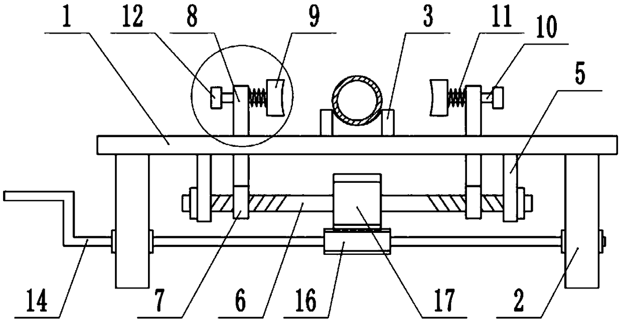
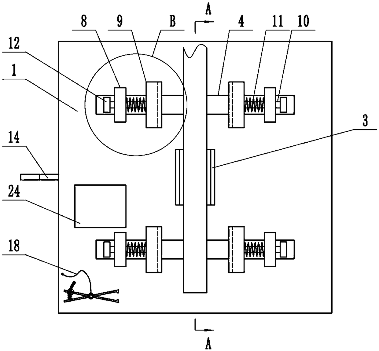
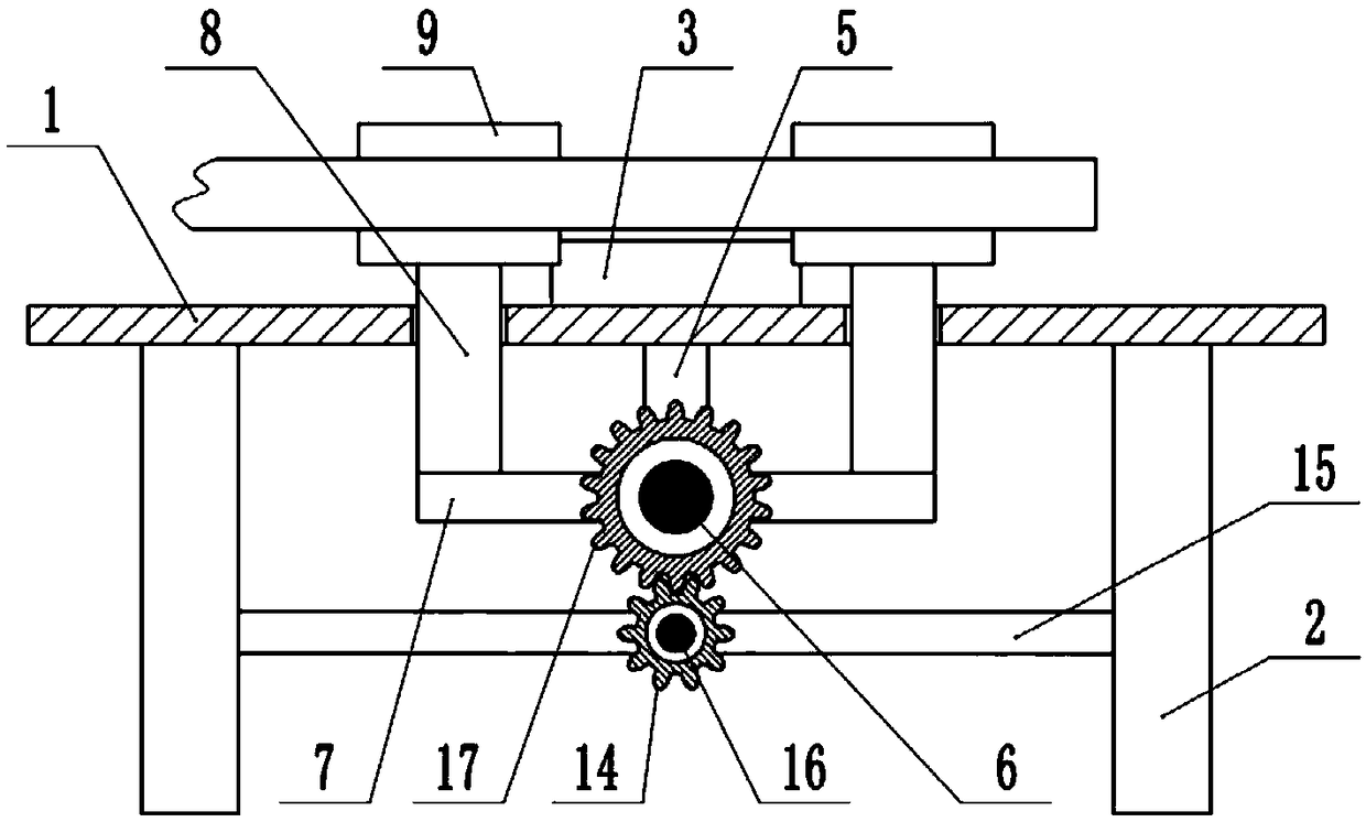
[0037]The reference signs in the drawings of the description include: fixed platform 1, outrigger 2, support seat 3, chute 4, fixed seat 5, two-way screw rod 6, slide plate 7, slider 8, fixed block 9, slide rod 10, Compression spring 11, limit block 12, milling plane 13, manual rocker 14, fixed plate 15, first spur gear 16, second spur gear 17, elastic rope 18, first measuring rod 19, second measuring rod 20, Back-moving spring 21, measuring ruler 22, observation slot 23, signboard 24.

[0038] The embodiment is basically as attached figure 1 Shown: clamping equipment for parts processing, including a fixed platform 1 set horizontally, four corners of the bottom of the fixed platform 1 are provided with outriggers 2, and the upper end of the fixed platform 1 is provided with a support seat 3 for initially placing steel pipes, and the support seat 3 There is an arc-shaped groove on ...


PUM


Abstract

The invention relates to the technical field of clamping devices, in particular to clamping equipment for part machining. The clamping equipment comprises a fixing platform; a fixing mechanism and a driving mechanism are arranged below the fixing platform; the fixing mechanism comprises two fixing seats; a transversely-arranged bidirectional screw rod is rotationally connected between the two fixing seats; a sliding plate is in threaded connection to each of two threaded parts of the bidirectional screw rod; two sliding blocks are arranged between the two sliding plates; fixing blocks for fixing steel pipes are arranged on the two sliding blocks; compression springs are fixedly connected between the fixing blocks and the sliding blocks; first measuring mechanisms are connected between thefixing blocks and the sliding blocks; and a second measuring mechanism is further fixed to the upper end of the fixing platform. The first measuring mechanisms are used for measuring the pre-tightening force on the clamped steel pipes in real time, the bidirectional screw rod is rotated, the pre-tightening force on the steel pipes is close to the reference pre-tightening force, and thus the pre-tightening force for clamping the steel pipes is measured, regulated and controlled.

Description

technical field [0001] The invention relates to the technical field of part clamping, in particular to a clamping device for part processing. Background technique [0002] Steel pipe refers to steel with a hollow section whose length is much longer than the diameter or circumference. As an economical steel, steel pipe is widely used in the fields of conveying fluid and powdery solid, exchanging heat energy, manufacturing mechanical parts and containers, etc. When processing steel pipes, especially when welding and cutting steel pipes, it is often necessary to clamp and fix the steel pipes before processing, but the diameters of steel pipes are different and the wall thicknesses of steel pipes are also different. When processing steel pipes, The pre-tightening force of fixing the steel pipe is determined by the hand feel of the worker, and this fixing method may cause the pre-tightening force of the steel pipe to be too large, causing the steel pipe to be deformed and damaged...

Claims


Application Information

Patent Timeline
IPC IPC(8): B25B11/00G01B5/06G01B5/08
CPCB25B11/00G01B5/06G01B5/08
Inventor 王显峰
Owner 重庆亿普机电有限公司
Why Eureka
Try Eureka