Hollow-sandwich multi-cavity steel pipe concrete member and preparation method thereof

A CFST and concrete technology, applied in bridge parts, bridge materials, bridges, etc., can solve the problems of decreased bearing capacity of CFST structures, many welding spots on the board surface, and buckling of steel pipes, and achieves reduction and improvement of structural steel consumption. Work performance, the effect of reducing maintenance costs

Pending Publication Date: 2019-03-01
CENT SOUTH UNIV
View PDF0 Cites 8 Cited by
  • Summary
  • Abstract
  • Description
  • Claims
  • Application Information

AI Technical Summary

Problems solved by technology

[0006] (2) The separation between the steel pipe wall and the concrete is obvious
The above phenomena will affect the interaction between the steel pipe and the core concrete, resulting in local buckling of the steel pipe, the failure of the core concrete to reach the three-dimensional compression state, and the decline in the bearing capacity of the steel pipe concrete structure.
[0008] (3) The weld quality of multi-cavity steel tube concrete is not easy to meet
However, due to the long length of the steel pipe and the need for continuous welding along the axial direction, it is easy to cause problems such as more solder joints on the plate surface, longer weld seams, and complex welding residual stress, and the quality of the weld seams is not easy to meet
Moreover, this method of welding along the entire length will consume a lot of manpower, and the overall performance of the steel pipe will be greatly affected.

Method used


Image

  • Hollow-sandwich multi-cavity steel pipe concrete member and preparation method thereof
  • Hollow-sandwich multi-cavity steel pipe concrete member and preparation method thereof
  • Hollow-sandwich multi-cavity steel pipe concrete member and preparation method thereof

Examples


Embodiment Construction

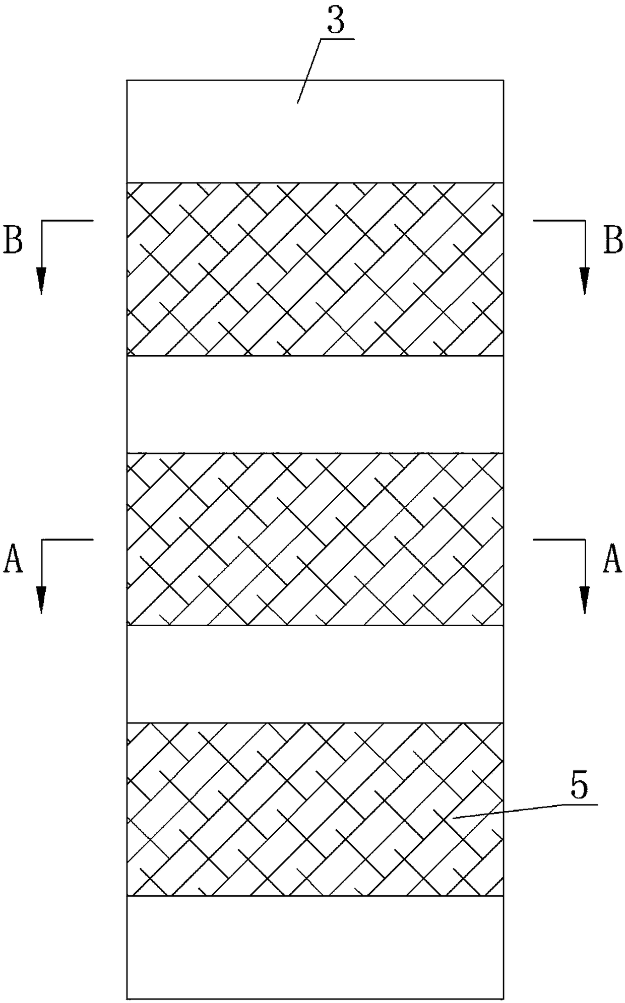
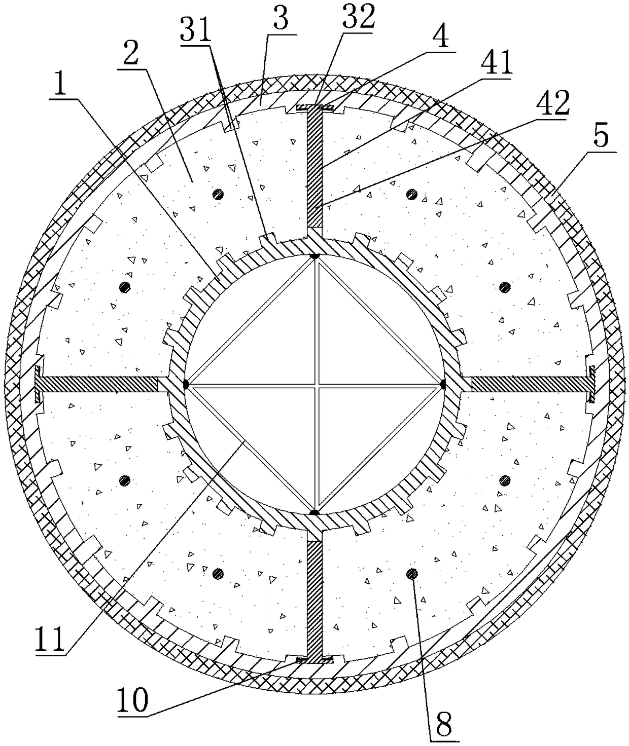
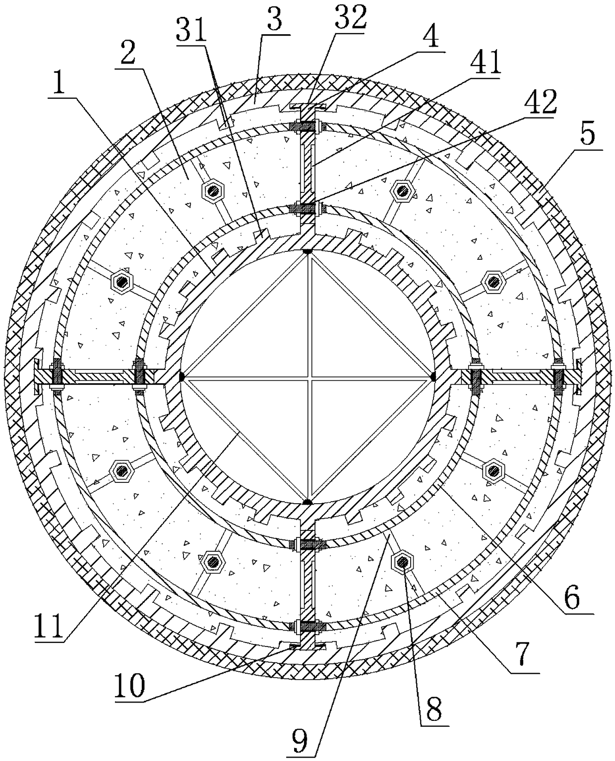
[0043] from Figure 1 to Figure 5It can be seen that the hollow interlayer multi-cavity steel pipe concrete member of the present invention includes a circular inner steel pipe 1, concrete 2, a circular outer steel pipe 3, a diaphragm 4, an outer cylinder 5, an arc inner tie rod 6, an arc External tie rod 7, prestressed rod 8, positioning steel bar 9, epoxy resin grout 10 and support iron 11,

[0044] There are four diaphragms 4, and each diaphragm 4 is vertically welded on the outer wall of the inner steel pipe 1 along the axis of the inner steel pipe 1. The four diaphragms 4 are evenly distributed around the axis of the inner steel pipe 1, and each diaphragm The length of the plate 4 is the same as that of the inner steel pipe 1, and each diaphragm 4 is arranged along the length of the inner steel pipe 1. The cross-section of the outer end of the diaphragm 4 is T-shaped, and on the front side of the diaphragm and the back side are axially evenly distributed with a number of...


PUM


Abstract

The invention discloses a hollow-sandwich multi-cavity steel pipe concrete member and a preparation method thereof. The hollow-sandwich multi-cavity steel pipe concrete member comprises an internal steel pipe and an external steel pipe which are concentrically placed; a space between the internal steel pipe and the external steel pipe is filled with concrete; a plurality of transverse diaphragms are uniformly distributed on the external wall of the internal steel pipe around the axis of the internal steel pipe; each transverse diaphragm is placed along the full length of the internal steel pipe in the axial direction; the external end part of each transverse diaphragm is in clamping connection with a groove formed in the internal wall of the external steel pipe; convex teeth are arranged on the internal wall of the external steel pipe and the external wall of the internal steel pipe; a plurality of shear grooves are uniformly formed in the side surfaces of the transverse diaphragms inthe axial direction; a plurality of external cylinders made of carbon fiber composite materials are bonded outside the external steel pipe in the annular direction; and the external cylinders are notconnected with the end part of the external steel pipe. According to the hollow-sandwich multi-cavity steel pipe concrete member, the corrosion resistance is high, less separation phenomena between the steel pipe walls and the concrete are less, the steel pipes are unlikely to generate local buckling, and the stressed states of the concrete in three directions are uniform.

Description

technical field [0001] The invention relates to the technical field of building structural components, in particular to a hollow interlayer multi-cavity steel pipe concrete component and a preparation method thereof. Background technique [0002] The concrete-filled steel tube structure is a component formed by filling concrete in steel tubes. It makes full use of the interaction between steel tubes and concrete in the process of stress: on the one hand, the steel tubes have a restraining effect on the core concrete, making the concrete in a three-dimensional compression state, thus effectively Improve the strength of concrete; on the other hand, the presence of concrete can effectively slow down and avoid premature local buckling of thin-walled steel pipes. In addition, the steel pipe can also be used as a template when pouring concrete. In recent years, the CFST structure has been favored by the engineering community due to its superior mechanical properties, and has been...

Claims


Application Information

Patent Timeline
Patent Type & Authority Applications(China)
IPC IPC(8): E01D19/00E04C3/34B23P15/00E01D101/26
CPCE01D19/00B23P15/00E01D2101/268E04C3/34
Inventor 周旺保余建蒋丽忠谭志化赖智鹏冯玉林张云泰聂磊鑫郑兰高路峻
Owner CENT SOUTH UNIV
Why Eureka
Try Eureka