Composite framework of ribbed beam floor system

A technology of dense-ribbed beam floor and combined formwork, which is applied to formwork/formwork/work frame, on-site preparation of building components, construction, etc. Easy to disassemble and fix

Inactive Publication Date: 2019-03-01
淄博和阳工贸有限公司
View PDF0 Cites 23 Cited by
  • Summary
  • Abstract
  • Description
  • Claims
  • Application Information

AI Technical Summary

Problems solved by technology

[0003] At present, the development of formwork has mainly gone through two generations. The first-generation formwork adopts disposable formwork, which is easy to fall off, return to alkali, break, and the wall thickness is not standard and easy to leak during construction; the second-generation formwork is fixed with nails, and the disassembly process is cumbersome. The secondary construction utilization rate is low, the construction cost is high, and the period is long; in addition, whether it is the first-generation formwork or the second-generation formwork, it is often used to pave or strip, that is, to lay the bottom form under the formwork as a whole or at intervals. Due to the lack of connection between the formwork, it is necessary to fill the gaps between the formwork with fillers such as bamboo plywood, wooden strips, and extruded plastic slats before pouring to prevent the formwork from falling under the lateral pressure of the concrete. Displacement, this process causes the formwork construction process to be cumbersome, and the removal of the formwork after pouring is complicated

Method used


Image

  • Composite framework of ribbed beam floor system
  • Composite framework of ribbed beam floor system
  • Composite framework of ribbed beam floor system

Examples


Embodiment Construction

[0032] The present invention will be further described below in conjunction with accompanying drawing.

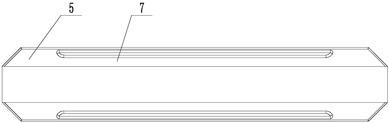
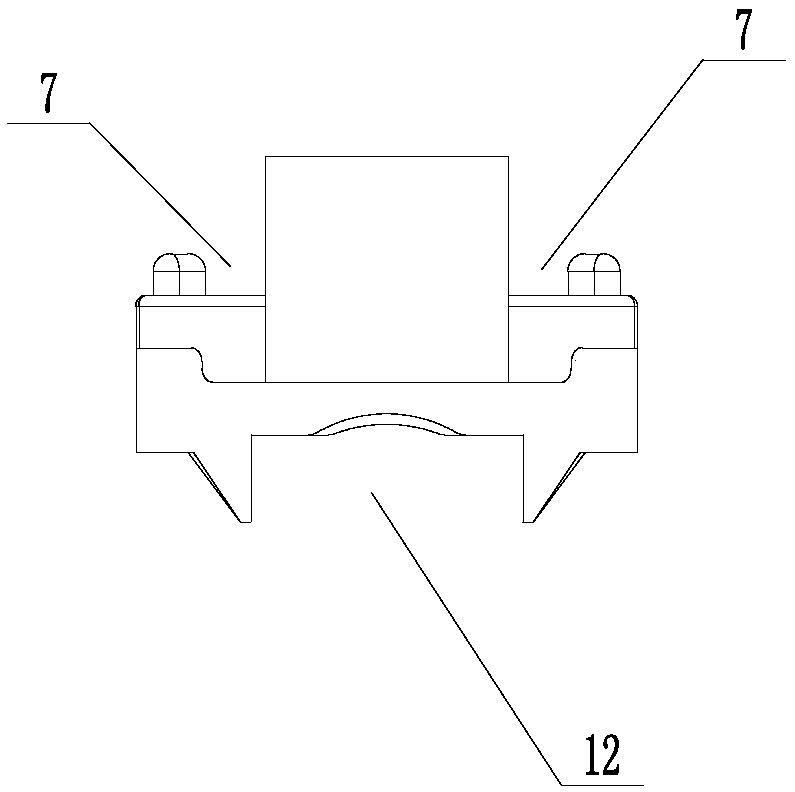
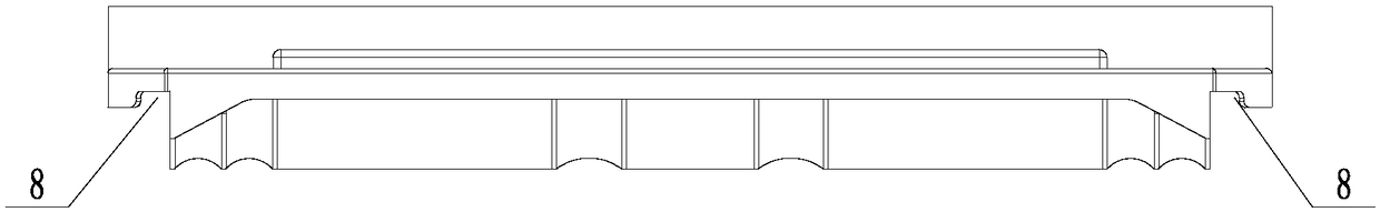
[0033] Such as Figure 1-12 As shown, the densely ribbed beam floor composite formwork of the present invention includes a connecting beam 1, a connecting block 2 detachably connected to the two short side ends of the connecting beam, and a formwork detachably connected to the two long side ends of the connecting beam 3. A plurality of connecting beams 1 and connecting blocks 2 are connected and extended circumferentially to form a mesh grid. The formwork 3 is arranged in the grid 4 of the mesh grid and is detachably connected to the long side ends of the connecting beams 1. The size and size are compatible with the grid 4; the connecting beam 1 includes a first base 5, the top of the first base 5 is respectively provided with first engaging parts along the two long sides, and the bottom of the first base 5 is arranged along the two short sides. A second engaging part is p...


PUM


Abstract

The invention relates to a building framework, in particular to a composite framework of a ribbed beam floor system. According to the composite framework of the ribbed beam floor system, connecting beams, connecting blocks and mold shells are connected to form a unified whole, the disassembly and assembly construction processes of full or strip pavement are simplified, thus disassembling and assembling and fixing of the mold shells, the connecting beams and the connecting blocks are convenient, and the composite framework can be recycled in construction of the ribbed beam floor system. The composite framework includes the connecting beams, the connecting blocks detachably connected to the two short edge ends of the connecting beams and the mold shells detachably connected to the two long edge ends of the connecting beams, the multiple connecting beams and the connecting blocks are connected to extend into a network grid in the circumferential direction, the mold shells are arranged ina grid of the network grid and are detachably connected with the long edge ends of the connecting beams, and the sizes and dimensions of the mold shells are adapted to the grid.

Description

technical field [0001] The invention relates to a building formwork, in particular to a composite formwork of densely ribbed beam floors. Background technique [0002] As a new formwork system, plastic formwork has been widely used in construction engineering in recent years. The densely ribbed floor system formed by plastic formwork has gradually replaced the traditional densely ribbed structure due to its excellent economic benefits. Compared with the traditional dense rib beam structure system, it has natural advantages such as simple construction, short cycle, low cost, novel appearance, and reduced noise. [0003] At present, the development of formwork has mainly gone through two generations. The first-generation formwork adopts disposable formwork, which is easy to fall off, return to alkali, break, and the wall thickness is not standard and easy to leak during construction; the second-generation formwork is fixed with nails, and the disassembly process is cumbersome....

Claims


Application Information

Patent Timeline
Patent Type & Authority Applications(China)
IPC IPC(8): E04G11/40E04G11/50
CPCE04G11/40E04G11/50
Inventor 邹建斌
Owner 淄博和阳工贸有限公司
Why Eureka
Try Eureka