Mine safety monitoring system based on computer control

A safety monitoring and computer technology, applied in the computer field, can solve the problems of increased operation difficulty, large dust, endangering life safety, etc., and achieve the effect of reducing operation difficulty, reasonable structure design, and improving safety.

Inactive Publication Date: 2019-03-01
南京福禄源电子科技有限公司
View PDF8 Cites 0 Cited by
  • Summary
  • Abstract
  • Description
  • Claims
  • Application Information

AI Technical Summary

Problems solved by technology

At present, most of the mine monitoring instruments in our country only have the early warning and monitoring functions of oxygen content and toxic gases, but in underground operations, the non-degradable dust will bring great personal hazards to workers and increase the difficulty of operation. Sometimes it may be due to the situation It is more serious that the life safety of the miners will be endangered if the miners do not respond. At this time, if the ground staff receives the alarm in time and takes rescue measures, the life safety of the miners will be greatly guaranteed.
[0003] Due to the complex environment in the mine, the drilling and installation operation of the data acquisition terminal is dangerous and inconvenient to use, and the dust in the mine is relatively large, which is likely to interfere with the work of the data acquisition terminal. Among them, the locations where accidents are prone to occur are also different, which leads to the need to change the location of the data acquisition terminal according to the actual monitoring needs. Therefore, we propose a mine safety monitoring system based on computer control

Method used


Image

  • Mine safety monitoring system based on computer control
  • Mine safety monitoring system based on computer control
  • Mine safety monitoring system based on computer control

Examples


Embodiment Construction

[0034] The following will clearly and completely describe the technical solutions in the embodiments of the present invention with reference to the accompanying drawings in the embodiments of the present invention. Obviously, the described embodiments are only some, not all, embodiments of the present invention. Based on the embodiments of the present invention, all other embodiments obtained by persons of ordinary skill in the art without creative efforts fall within the protection scope of the present invention.

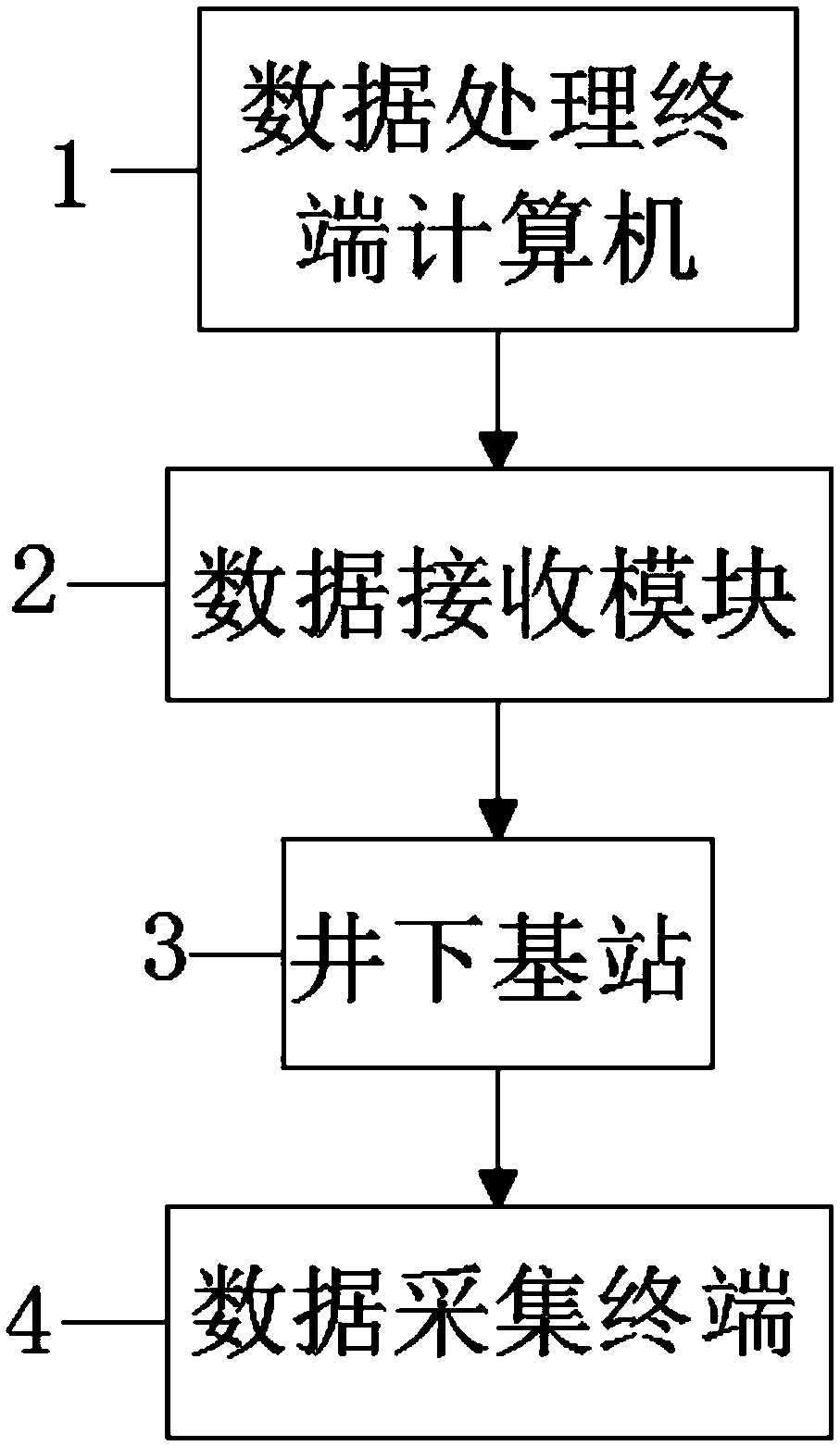
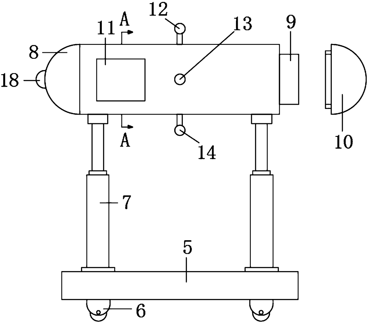
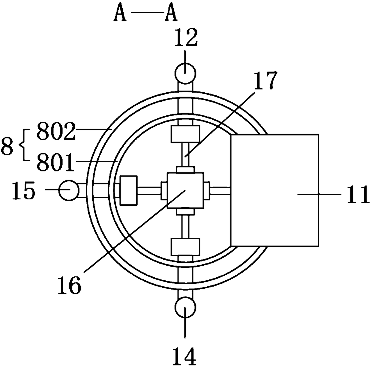
[0035] see Figure 1-4As shown, this embodiment is a mine safety monitoring system based on computer control, including a data processing terminal computer 1, the data processing terminal computer 1 is electrically connected to a data receiving module 2, and the electrical input is connected to an underground base station 3, and the underground base station 3. The electrical input is connected with a data collection terminal 4, and the place of use of the data coll...


PUM


Abstract

The invention discloses a mine safety monitoring system based on computer control. The mine safety monitoring system comprises a data processing terminal computer which is connected with a data receiving module in an electric input mode, the data receiving module is connected with a downhole base station in an electric input mode, and the downhole base station is connected with a data collecting terminal in an electric input mode; the data collecting terminal comprises a moving base, moving wheels are arranged at the bottom of the moving base, pneumatic telescopic rods are symmetrically arranged on the left side and the right side of the top of the moving base, and a monitoring box is arranged at the tops of the two sets of pneumatic telescopic rods. An external-thread pipe seat is arranged on the right side of the monitoring box, a sealing cover is arranged on the right side of the external-thread pipe seat, a dust concentration detector is arranged on the left side of the surface ofthe monitoring box, an air pressure sensor is arranged at the top of an inner cavity of the monitoring box, and a temperature sensor is arranged on the front side of the inner cavity of the monitoringbox. The mine safety monitoring system is reasonable in structure design, the data collecting terminal does not need to be fixedly installed, operation difficulty and danger are lowered, and movableuse is facilitated.

Description

technical field [0001] The invention relates to the field of computer technology, in particular to a mine safety monitoring system based on computer control. Background technique [0002] With the development of social science and technology, computers have also developed rapidly and are gradually applied to various fields of our life and work. Mine is the general term for the shafts, chambers, equipment, ground buildings and structures that form the underground coal mine production system. Sometimes the inclined shafts, shafts, and adits in the underground development of mines are also called mines. The determination of the size of each mine field, production capacity and service life of each mine is one of the key issues that must be resolved in the design of the mine itself. At present, most of the mine monitoring instruments in our country only have the early warning and monitoring functions of oxygen content and toxic gases, but in underground operations, the non-degra...

Claims


Application Information

Patent Timeline
Patent Type & Authority Applications(China)
IPC IPC(8): E21F17/18
CPCE21F17/18
Inventor 朱景超马常建马彩霞
Owner 南京福禄源电子科技有限公司
Why Eureka
Try Eureka