Gear maintenance hydraulic control system and gearbox

A technology of hydraulic control system and gearbox, applied in transmission control, components with teeth, belts/chains/gears, etc., can solve problems such as immobility, hidden dangers, power failure of gearboxes, etc., to improve driving. Safety factor, avoidance of sudden changes in vehicle speed, and effect of maintaining vehicle speed

Active Publication Date: 2019-03-01
SHENGRUI TRANSMISSION
View PDF7 Cites 2 Cited by
  • Summary
  • Abstract
  • Description
  • Claims
  • Application Information

AI Technical Summary

Problems solved by technology

[0004] The purpose of the present invention is to provide a gear holding hydraulic control system to solve the problem in the prior art that the

Method used


Image

  • Gear maintenance hydraulic control system and gearbox
  • Gear maintenance hydraulic control system and gearbox
  • Gear maintenance hydraulic control system and gearbox

Examples


Embodiment 1

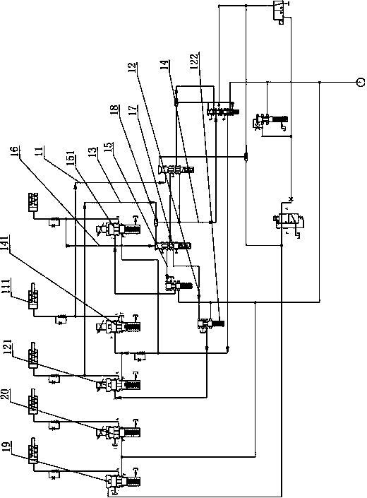
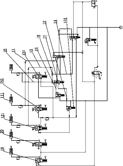
[0039] like Figure 1-Figure 3As shown, the gear holding hydraulic control system provided by the present invention includes a first oil passage 11, a second oil passage 12, a third oil passage 13, a fourth oil passage 14, a fifth oil passage 15 and a sixth oil passage 16 ; The first clutch 111 is provided on the first oil circuit 11, the first brake control valve 121 is provided on the second oil circuit 12, and the normal high solenoid valve 141 is provided on the fourth oil circuit 14, so The fifth oil passage 15 is provided with a second clutch control valve 151; the first oil passage 11 is connected with the second oil passage 12, one end of the third oil passage 13 is connected with the second oil passage 12, and the other end is connected with the second oil passage 12. The fourth oil passage 14 is connected, the fifth oil passage 15 is connected with the first oil passage 11, one end of the sixth oil passage 16 is connected with the fifth oil passage 15, and the other ...

Embodiment 2

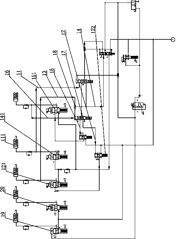
[0061] like Figure 4 As shown, in this embodiment, the difference between the gear holding hydraulic control system and the first embodiment is that it also includes the second brake control valve 19, the third brake control valve 20 and the fourth brake 21; the first clutch 111, the second brake The first brake, the second brake, the third brake, the fourth brake 21 and the second clutch form eight gears of the gearbox.

[0062] The first clutch 111, the first brake, the second brake, the third brake, the fourth brake 21 and the second clutch form the eight gears of the gearbox, and the cooperation between the fixed actuators forms the gearbox output gear to ensure that the vehicle runs in eight gears.

[0063]Further, the first brake can sequentially form the output of five gears in the first gear interval of the gearbox with the second brake, the fourth brake, the third brake, the first clutch 111, and the second clutch respectively; The second clutch can form three gear...


PUM


Abstract

The invention provides a gear maintenance hydraulic control system and a gearbox. A first oil way is connected with a second oil way; one end of a third oil way is connected with the second oil way, and the other end is connected with a fourth oil way; a fifth oil way is connected with the first oil way; one end of a sixth oil way is connected with the fifth oil way, and the other end is connectedwith the fourth oil way; when the gearbox loses power in a first gear section, a normally high electromagnetic valve is conducted to generate oil pressure, a first clutch enables a first brake control valve to obtain the oil pressure through the second oil way, the normally high electromagnetic valve generates the oil pressure through the fourth oil way, and a first brake is combined with the first clutch to enable the gearbox to output a first gear; when the gearbox loses power in a second gear section, the normally high electromagnetic valve is conducted to generate the oil pressure, a second clutch control valve obtains the oil pressure through the fifth oil way, and a second clutch is combined with the first clutch to enable the gearbox to output a second gear; the lowest gear in thesecond gear section is higher than the highest gear in the first gear section; and the second gear is higher than the first gear.

Description

technical field [0001] The invention relates to the technical field of automobiles, in particular to a gear holding hydraulic control system and a gearbox. Background technique [0002] The car gearbox can generate multiple gears of the car through the variable speed transmission and the operating mechanism, mainly to realize the car's starting, idling stop, low speed, high speed, acceleration, deceleration, climbing and reversing operations. [0003] Existing cars include multiple forward gears, which enable the car to run at low speed and high speed when driving; when the gearbox is powered off, the car will lose power, resulting in the vehicle being unable to move forward and can only wait for the towing company; and when the vehicle is in When driving in a higher forward gear, there is no safe limp home gear to lose power, and it is more dangerous to lose power when overtaking. Due to the power failure of the gearbox, the vehicle stops suddenly, and the driver will lean ...

Claims


Application Information

Patent Timeline
IPC IPC(8): F16H61/40F16H61/02
CPCF16H61/0262F16H61/40
Inventor 张广瀚杨震黄友宾付鑫亮
Owner SHENGRUI TRANSMISSION
Why Eureka
Try Eureka