Driving mechanism of bevel gear transmission pipeline robot

A pipeline robot and driving mechanism technology, applied in the direction of special pipes, pipe components, mechanical equipment, etc., can solve the problems of slow speed and low efficiency, and achieve the effect of enhanced driving force and low density

Pending Publication Date: 2019-03-01
南京管科智能科技有限公司
View PDF1 Cites 0 Cited by
  • Summary
  • Abstract
  • Description
  • Claims
  • Application Information

AI Technical Summary

Problems solved by technology

[0004] The purpose of the present invention is to provide a driving mechanism for a bevel gear transmission pipeline ro

Method used


Image

  • Driving mechanism of bevel gear transmission pipeline robot
  • Driving mechanism of bevel gear transmission pipeline robot
  • Driving mechanism of bevel gear transmission pipeline robot

Examples


Example Embodiment

[0047] In order to make the purpose and technical solution of the present invention clearer, the technical solution of the present invention will be clearly and completely described below in conjunction with the embodiments of the present invention.

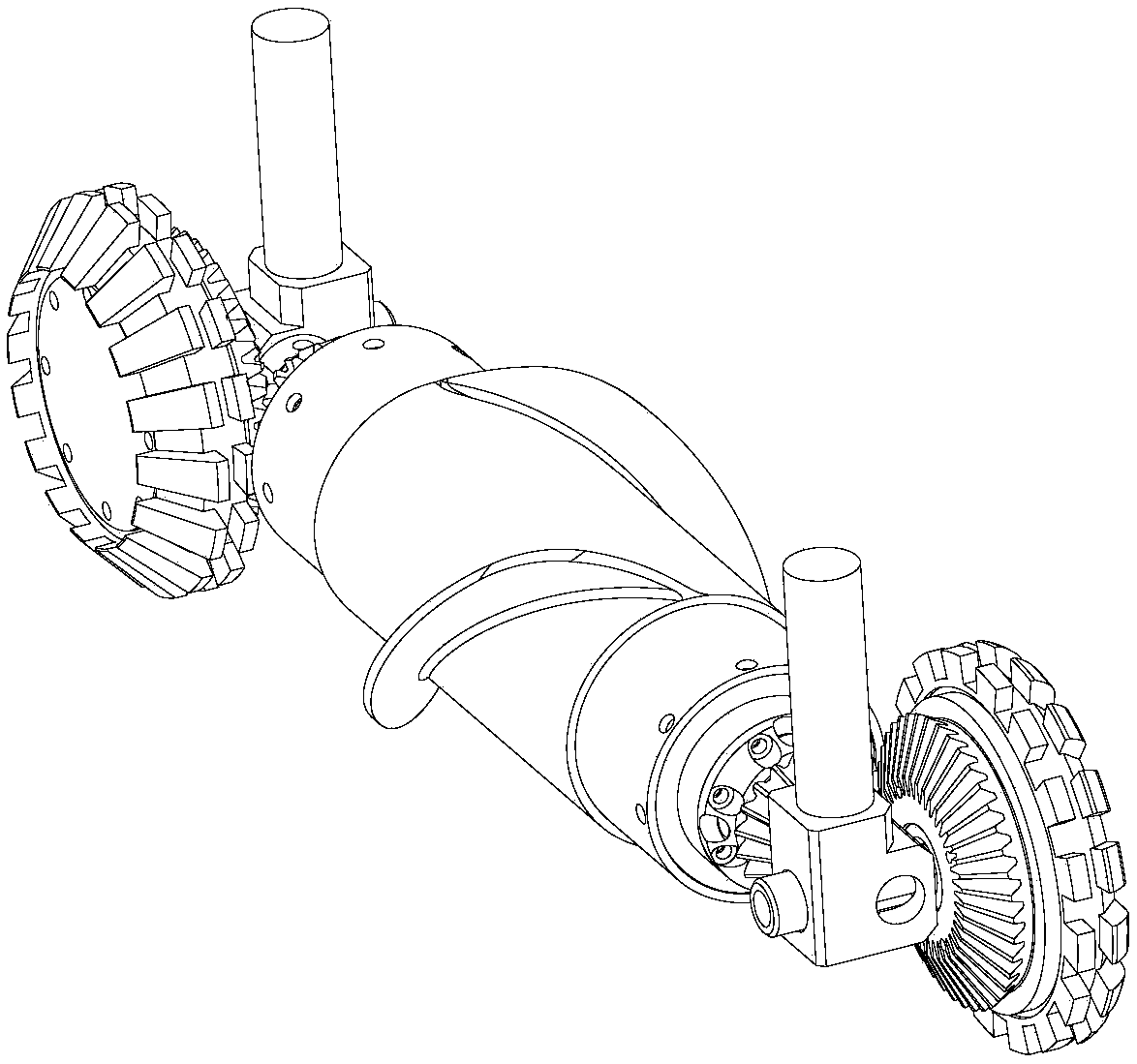
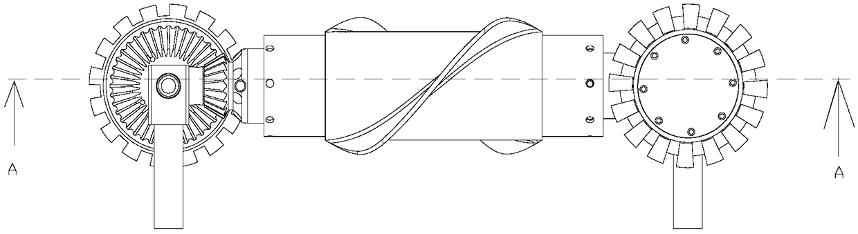
[0048] like Figure 1-12 As shown, a driving mechanism of a bevel gear transmission pipeline robot includes a driving roller and two driving rollers arranged at both ends of the driving roller.

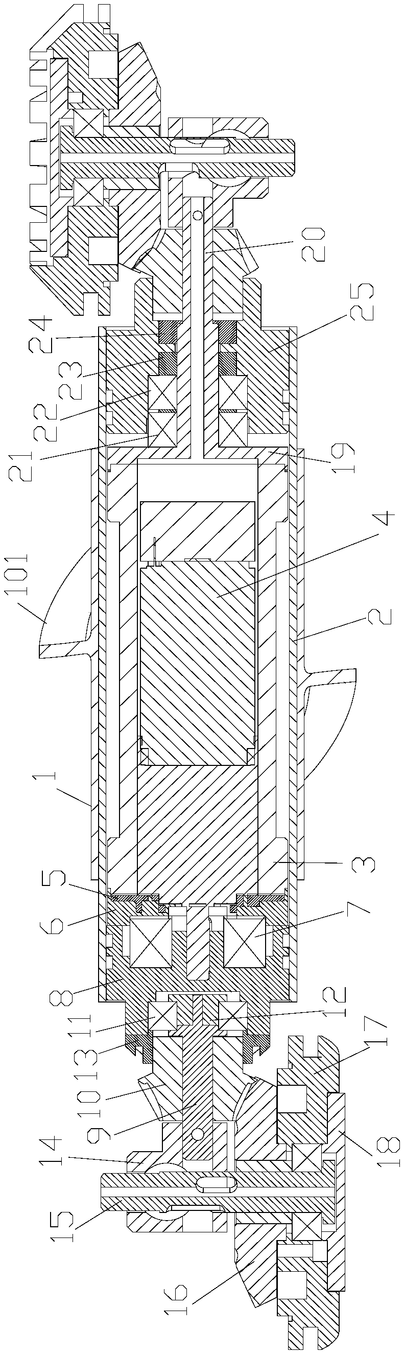
[0049] Each driving roller comprises a first bevel gear 10, a second bevel gear 16, a first connecting piece 14 and a roller 17. One end of the first bevel gear 10 protrudes outward along the axial direction to form a boss 1001, and the center of the boss 1001 There is a first through hole 1002 through the first bevel gear along the axial direction; the first connecting piece 14 is fixedly connected with the first rotating shaft 15, and the second bevel gear 16 and the roller 17 are sleeved on the first rotating shaft 15, and the first b...


PUM


Abstract

The invention discloses a driving mechanism of a bevel gear transmission pipeline robot. The driving mechanism comprises a driving drum and two driving rollers arranged at both ends of the driving drum. Each driving roller includes a first bevel gear, a second bevel gear, a first connecting part and a roller. One ends of the first bevel gears protrude outward and extend to form convex platforms inthe axis direction. The centers of the convex platforms are provided with first through holes penetrating through the first bevel gears in the axis direction. The first connecting parts are fixedly connected with first rotating shafts. The first rotating shafts are rotatably sleeved with the second bevel gears and the rollers. The first bevel gears are engaged with the second bevel gears. The second bevel gears are fixedly connected with the rollers coaxially. The radiuses of the second bevel gears are less than the radiuses of the rollers. The structure by adopting bevel gear transmission isdesigned, and the ratio of the number of teeth of the first bevel gears to the second bevel gears is 1:(1.5-5). The ratio of the number of the teeth has a larger torque, so that the driving force isenhanced, and the stable motion of the pipeline robot is ensured.

Description

technical field [0001] The invention relates to a driving mechanism of a bevel gear transmission pipeline robot. Background technique [0002] The environment of municipal pipelines is very harsh, and after long-term use, it is prone to corrosion, fatigue damage, or potential internal defects of the pipeline to develop into damage and cause leakage accidents, etc., especially for water pipelines, which are also prone to blockage and other accidents. Therefore, the in-pipe detection and desilting of pipelines is a very important practical project. At present, most of the in-pipe detection and decontamination are performed manually, which is limited by factors such as the size of the pipeline and the harsh environment, resulting in high work intensity and low work efficiency. The problem currently arises with pipeline bots. [0003] The existing patent discloses a pipeline robot driving device, application number: 201810153336X, which uses a wheel-spiral blade roller-Mecanum ...

Claims


Application Information

Patent Timeline
IPC IPC(8): F16L55/32F16L101/12F16L101/30
CPCF16L55/32F16L2101/12F16L2101/30
Inventor 娄保东
Owner 南京管科智能科技有限公司
Why Eureka
Try Eureka