
Substrate clamp for film stress test

A technology of film stress and substrate clamping, which is applied in the measurement of the change force of optical properties of the material when it is stressed, can solve the problems of poor coating effect, large influence on the coating surface, troublesome operation, etc.

Pending Publication Date: 2019-03-01
SHENZHEN INST OF ADVANCED TECH
View PDF0 Cites 0 Cited by
  • Summary
  • Abstract
  • Description
  • Claims
  • Application Information

AI Technical Summary

Problems solved by technology

[0006] An object of the present invention is to provide a kind of substrate fixture for thin film stress test, to solve the problem in the prior art that the samples (strips) used for coating can only have one side for coating, and the other side must be completely shielded. The operation brings unnecessary troubles, and at the same time, the coating surface is greatly affected by the fixture, which makes the coating effect poor.

Method used


Image

  • Substrate clamp for film stress test
  • Substrate clamp for film stress test
  • Substrate clamp for film stress test

Examples


Embodiment 1

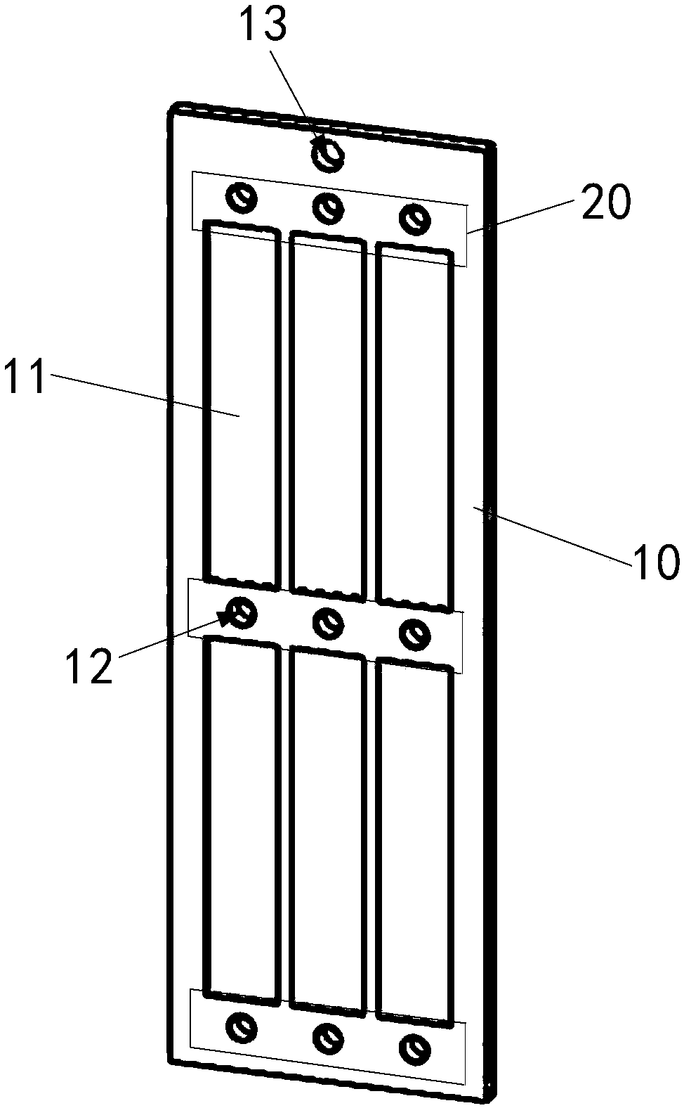
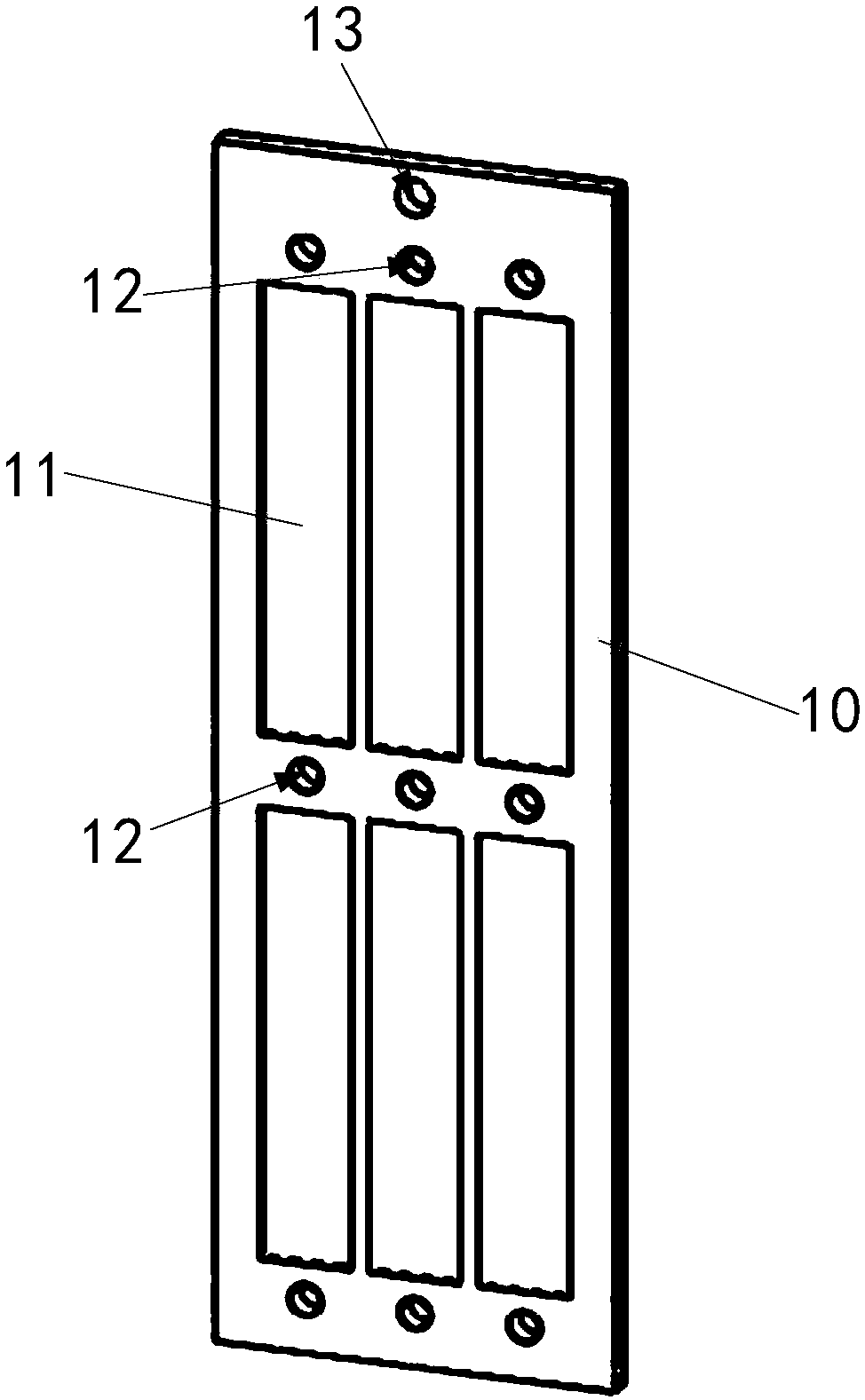
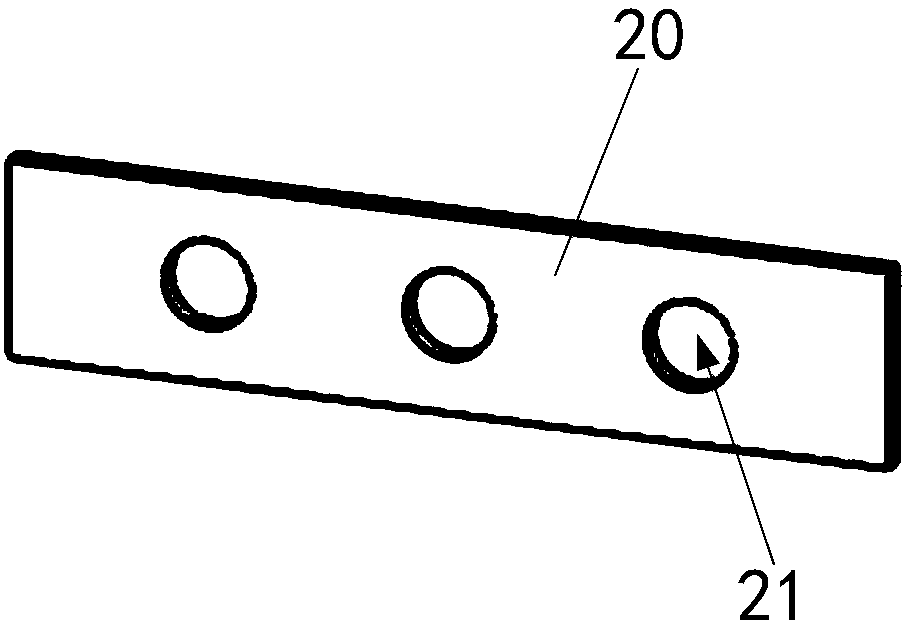
[0037] Such as Figure 1-4 As shown, the substrate fixture for film stress testing provided in this embodiment includes a base 10 and a clip 20;

[0038] The base 10 is provided with a plurality of clamping parts, and two ends of each clamping part are respectively provided with clamping holes 12;

[0039] The clip 20 is provided with a connecting hole 21, and the connector passes through the connecting hole 21 and the clamping hole 12 in turn, so that the sample 30 to be coated is fixed on the clamping part, and one end of the base 10 Hanging holes 13 are also provided.

[0040] In the substrate fixture for film stress testing provided by the embodiment of the present invention, the base 10 is provided with a plurality of clamping parts, the two ends of each clamping part are respectively provided with clamping holes 12, and the clip 20 is provided with The connecting hole 21, the connecting piece passes through the connecting hole 21 and the clamping hole 12 in turn, so th...


PUM


Abstract

The invention provides a substrate clamp for a film stress test and belongs to the technical field of clamps. The substrate clamp comprises a base and a clamping piece; wherein the base is provided with a plurality of clamping portions; every two ends close to each clamping portion are provided with clamping holes; the clamping piece is provided with a connecting hole; a connecting member successively passes through the connecting hole and the clamping holes to fix a sample to be coated to the clamping portion; and one end of the base is further provided with a hanging hole. In the present solution, the clamping portions may be flat grooves, and the connecting member successively passes through the connecting hole and the clamping holes to fix the sample to be coated to the flat groove, thereby ensuring that a coated surface is affected by a tool as little as possible, and the back side of sample is completely shielded, which solves the problem that a sample (in a long strip shape) inthe prior art only has one side coated, and the other side completely shielded so as to bring unnecessary trouble to the operation, and the coated surface is seriously affected by the clamp and is poor in coating effect.

Description

technical field [0001] The invention relates to the technical field of fixtures, in particular to a substrate fixture for thin film stress testing. Background technique [0002] At present, thin film materials are widely used in many fields such as microelectronics, semiconductors, photovoltaic energy, aerospace, automobiles, and mechanical processing, and their importance is becoming increasingly prominent; It is necessary to make priority deployment and key breakthroughs in key areas such as "information technology, high-end equipment manufacturing, new energy, new materials, and new energy vehicles" (Guo Fa [2012] No. 28); and most key development areas are related to thin-film material technology Therefore, it is of great significance to vigorously carry out related research on thin film materials to promote the development of national key industries. [0003] The interfacial bonding strength and thermal fatigue resistance of thin film materials are closely related to t...

Claims


Application Information

Patent Timeline
Patent Type & Authority Applications(China)
IPC IPC(8): G01L1/24
CPCG01L1/24
Inventor 唐永炳石磊蒋春磊
Owner SHENZHEN INST OF ADVANCED TECH
Learn More