
Method for judging measuring result of platelet aggregation rate and calibration method of platelet aggregator

A technology for platelet aggregation and measurement results, which is applied in the medical field, can solve the problems of unreliable aggregation rate, cumbersome operation, and inability to accurately reflect platelet aggregation function, and achieve the effect of streamlining the test process and saving equipment resources

Active Publication Date: 2019-03-01
山东泰利信医疗科技有限公司
View PDF12 Cites 3 Cited by
  • Summary
  • Abstract
  • Description
  • Claims
  • Application Information

AI Technical Summary

Problems solved by technology

[0005] The platelet aggregation rate measured by the existing method is stable when the platelet concentration in the blood sample reaches a certain level, but if the platelet concentration is less than a certain value, the aggregation rate will also decrease, making the instrument report The aggregation rate is unreliable and cannot accurately reflect the platelet aggregation function. At present, before performing the platelet aggregation function test, hospitals generally use a hematology analyzer to count the platelets first, so as to measure the platelet concentration. If the measured value is higher than a certain When the value is higher, the platelet aggregation rate result obtained from the measurement is a reliable value, otherwise, it will report a doubtful result
This method is cumbersome to operate, and requires the use of extra blood analyzers and other instruments, and it is impossible to obtain the results at one time when measuring the platelet aggregation rate.

Method used


Image

  • Method for judging measuring result of platelet aggregation rate and calibration method of platelet aggregator
  • Method for judging measuring result of platelet aggregation rate and calibration method of platelet aggregator

Examples


Embodiment Construction

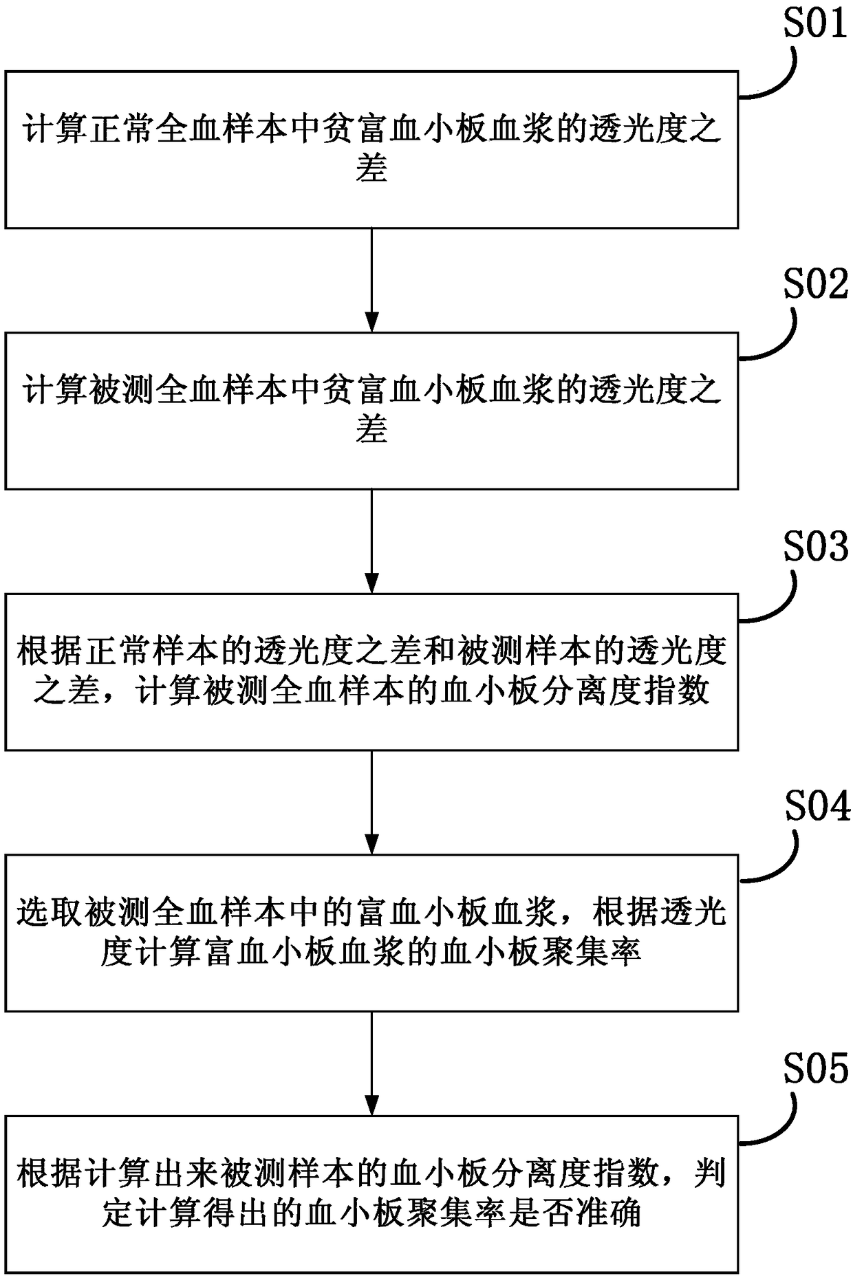
[0027] The main purpose of the present invention is to provide a method for determining the measurement result of platelet aggregation rate. By referring to the platelet separation degree parameter when separating platelets, the detection and calibration of platelet concentration can be realized, so that when measuring the platelet aggregation rate, the measurement As a result, more accurate and reliable judgments are made.

[0028] Below, refer to figure 1 Shown, the present invention is described in detail.

[0029] Such as figure 1 As shown in the flow chart of the method for determining the measurement result of platelet aggregation rate, the present invention proposes a method for determining the measurement result of platelet aggregation rate, comprising the following steps:

[0030] S01: Select normal whole blood samples, separate platelet-poor plasma and platelet-rich plasma according to standard operating procedures, measure platelet-poor plasma transmittance PPP0 a...


PUM


Abstract

The invention provides a method for judging the measuring result of the platelet aggregation rate. The method comprises the following steps: a normal whole blood sample is selected, the anaemic platelet plasma transmittance PPP0 and the blood-rich platelet plasma transmittance PRP0 are measured, and the transmittance difference P0 of the whole blood sample is calculated, wherein P0=PPP0-PRP0; a measured whole blood sample is selected, the anaemic platelet plasma transmittance PPP and the blood-rich platelet plasma transmittance PRP are measured, and the transmittance difference P of the measured sample is calculated, wherein P=PPP-PRP; the platelet separation degree index DI of the measured sample is calculated, wherein DI=P / P0=(PPP-PRP) / (PPP0-PRP0); the platelet aggregation rate of blood-rich platelet plasma is measured through a platelet aggregator; and whether the measured platelet aggregation rate is reliable or not is judged according to the platelet separation degree index DI ofthe measured sample. According to the method for judging the measuring result of the platelet aggregation rate, by referring to the platelet separation degree index of the measured sample, the measuring result of the platelet aggregation rate of the measured sample is judged reliably.

Description

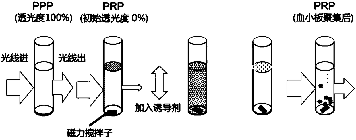
technical field [0001] The invention relates to the field of medical technology, in particular to a method for judging a platelet aggregation rate measurement result and a calibration method suitable for a platelet aggregation meter. Background technique [0002] Optical turbidimetry is a more practical and easy-to-promote clinical method for detecting platelet aggregation. This method is simple to operate, inexpensive, and well correlated with clinical events. It is the gold standard for detecting platelet aggregation. [0003] Platelet-rich plasma (PRP) is a suspension of platelets in plasma. The platelets are evenly dispersed, and the turbidity is proportional to the number of platelets contained in the plasma. When the platelet aggregation inducer is added, the inducer and platelet The above receptors bind, the platelets are activated, and the platelets deform to further release endogenous substances, resulting in aggregation and increased light transmittance. The higher...

Claims


Application Information

Patent Timeline
IPC IPC(8): G01N21/59
CPCG01N21/274G01N21/59
Inventor 谢凡陈生邱焕波
Owner 山东泰利信医疗科技有限公司
Learn More