Automatic gain control receiving component

An automatic gain control and component technology, applied in electrical components, transmission systems, radio wave measurement systems, etc., can solve the problem of inability to control pulse modulation signals and narrow pulse modulation signals normally.

Active Publication Date: 2019-03-01
BEIJING INST OF REMOTE SENSING EQUIP
View PDF8 Cites 1 Cited by
  • Summary
  • Abstract
  • Description
  • Claims
  • Application Information

AI Technical Summary

Problems solved by technology

[0004] The purpose of the present invention is to provide an automatic gain control receiving component, which solves the problem that the traditional automati

Method used


Image

  • Automatic gain control receiving component

Examples


Embodiment Construction

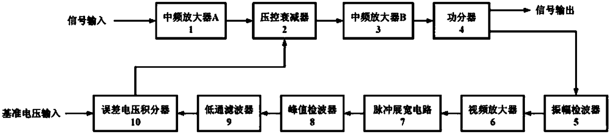
[0011] An automatic gain control receiving assembly, comprising: intermediate frequency amplifier A1, voltage-controlled attenuator 2, intermediate frequency amplifier B3, power divider 4, video amplifier 6, low-pass filter 9 and error voltage integrator 10, is characterized in that also includes : amplitude detector 5, pulse width stretching circuit 7 and peak detector 8.

[0012] The input end of the intermediate frequency amplifier A1 is the input end of the automatic gain control receiving component, the output end of the intermediate frequency amplifier A1 is connected with the input end of the voltage-controlled attenuator 2, the output end of the voltage-controlled attenuator 2 is connected with the input end of the intermediate frequency amplifier B3, and the intermediate frequency amplifier B3 The output end is connected with the sum port of the power divider 4, the power divider port one of the power divider 4 is the output end of the automatic gain control receiving ...


PUM


Abstract

The invention discloses an automatic gain control receiving component, comprising: an intermediate frequency amplifier A (1), a voltage controlled attenuator (2), an intermediate frequency amplifier B(3), a power divider (4), a video amplifier (6), and a low-pass filter (9), an error voltage integrator (10), an amplitude detector (5), a pulse width expanding circuit (7), and a peak detector (8).By using the amplitude detector (5), the pulse width expanding circuit (7) and the peak detector (8) in an automatic gain control loop, the automatic gain control receiving component achieves the automatic gain control of pulse modulated signal reception, especially narrow pulse modulation signal reception.

Description

technical field [0001] The invention relates to a receiving component, in particular to an automatic gain control receiving component. Background technique [0002] Automatic gain control is one of the most important functional circuits of radar receivers. The main purpose of automatic gain control is to adjust the gain of the receiver according to the strength of the received signal. When receiving a weak signal, the receiver has a high enough gain to ensure the detection of long-distance targets; when receiving a strong signal, the gain of the receiver is reduced as the signal increases to improve the dynamic range of the receiver. [0003] The traditional automatic gain control receiving components are composed of amplifiers, attenuators, envelope detectors, low-pass filters and error voltage integrators, etc., which can perform normal automatic gain control on continuous wave receiving signals, but cannot control pulse modulation signals Especially narrow pulse modulati...

Claims


Application Information

Patent Timeline
IPC IPC(8): G01S7/34H04B1/16
CPCH04B1/16G01S7/34
Inventor 袁明明凡守涛
Owner BEIJING INST OF REMOTE SENSING EQUIP
Why Eureka
Try Eureka