Unmanned aerial vehicle tracking motion system and method based on binocular vision distance measurement

A moving target and binocular vision technology, applied in the field of UAV tracking, can solve the problem of being unable to track non-cooperative moving targets in the air, and achieve high real-time performance and easy implementation

Pending Publication Date: 2019-03-01
BEIJING MECHANICAL EQUIP INST
View PDF8 Cites 19 Cited by
  • Summary
  • Abstract
  • Description
  • Claims
  • Application Information

AI Technical Summary

Problems solved by technology

[0004] In view of the above-mentioned analysis, the present invention aims to provide a system and method for tracking moving targets of unmanned aerial ve

Method used


Image

  • Unmanned aerial vehicle tracking motion system and method based on binocular vision distance measurement
  • Unmanned aerial vehicle tracking motion system and method based on binocular vision distance measurement

Examples


Embodiment 1

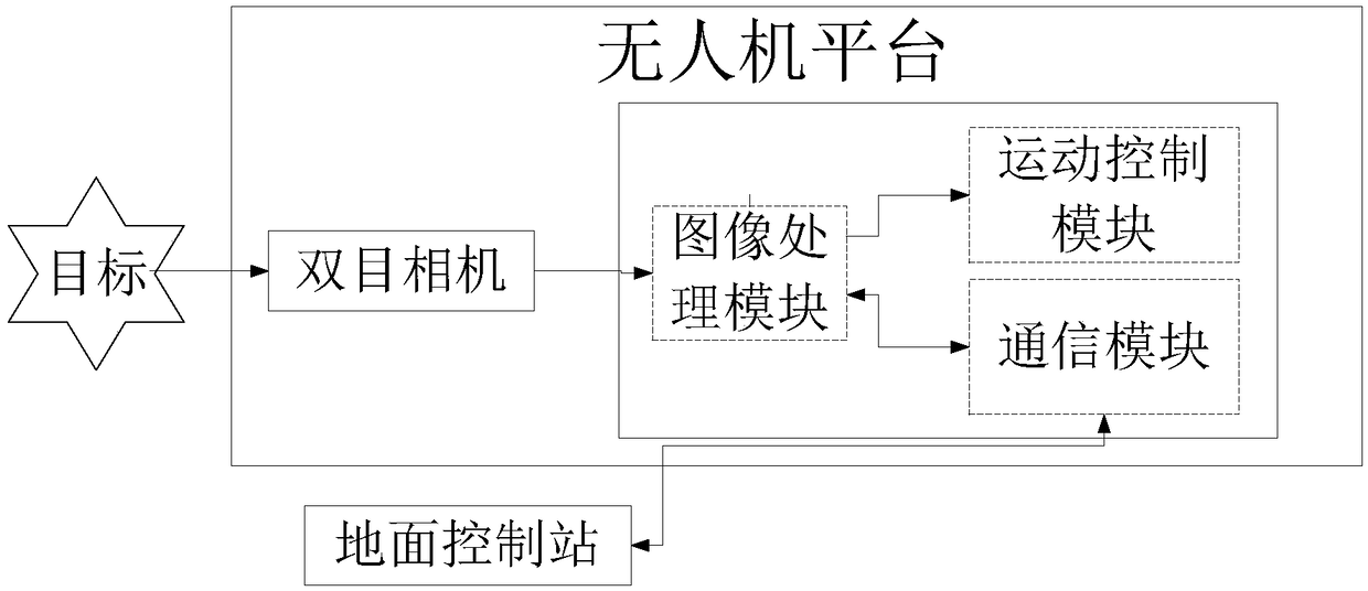
[0048] A specific embodiment of the present invention discloses a UAV tracking moving target system based on binocular vision ranging, such as figure 1 As shown, including: UAV platform, ground control station;

[0049] The unmanned aerial vehicle platform acquires images of moving targets in real time through binocular cameras, performs reference image tracking and binocular stereo matching, obtains the spatial three-dimensional coordinates of moving targets, and automatically approaches and tracks moving targets;

[0050] The ground control station is used to guide the UAV platform to initially approach the moving target, receive and display the moving target image sent by the UAV platform, and perform preliminary calibration on the target area in the image.

[0051]During implementation, after using the ground control station and other auxiliary equipment to guide the UAV platform to initially approach the moving target, after the moving target enters the field of view of t...

Embodiment 2

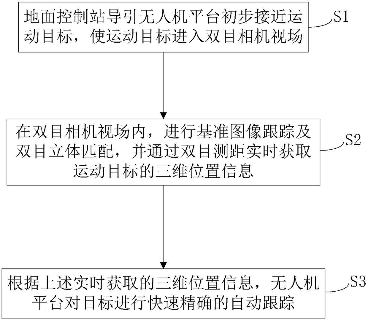
[0062] This embodiment discloses a method for tracking a moving target based on binocular vision distance measurement using the system in Embodiment 1, such as figure 2 shown, including the following steps:

[0063] Step S1, the ground control station guides the UAV to initially approach the target, so that the target enters the field of view of the binocular camera;

[0064] Step S2, in the field of view of the binocular camera, perform reference image tracking and binocular stereo matching, and obtain the three-dimensional position information of the moving target in real time through binocular ranging;

[0065] Step S3, according to the 3D position information obtained in real time, the UAV platform performs fast and accurate automatic tracking of the target.

[0066] Compared with the prior art, the binocular vision distance measurement-based UAV tracking moving target method provided by this embodiment uses a binocular camera for three-dimensional positioning of the tar...


PUM


Abstract

The present invention relates to an unmanned aerial vehicle tracking motion system and method based on binocular vision distance measurement, belonging to the technical field of unmanned aerial vehicle tracking. The problem is solved that non-cooperative moving objects cannot be tracked in the air in the prior art. The system comprises: an unmanned aerial vehicle platform configured to obtain moving object images in real time through a binocular camera to perform standard image tracking and binocular three-dimensional matching, obtain space three-dimensional coordinates of the moving objects and perform automatic approaching and tracking of the moving objects; and a ground control station configured to guide the unmanned aerial vehicle platform to primarily approach to the moving objects to receive and display the moving object images sent by the unmanned aerial vehicle platform and perform primary calibration for a target area in the images. The unmanned aerial vehicle tracking motionsystem and method employs a binocular camera to perform three-dimensional location of the target, has non-contact high-frequency measurement, is simple to implement and high in timeliness, can control the unmanned aerial vehicle to accurately and automatically approach to and track non-cooperative moving object through the position information of the moving object obtained in real time so as to provide basis for the processing of the moving object by the unmanned aerial vehicle in future.

Description

technical field [0001] The invention relates to the technical field of UAV tracking, in particular to a system and method for UAV tracking moving targets based on binocular vision ranging. Background technique [0002] In recent years, with the development of drone technology, the rapid expansion of "low, slow and small" aircraft in the military and civilian fields is easy to be used by criminals for illegal investigations, leaflets and even terrorist attacks, which has brought great impact to public safety and social stability. Hidden danger. Therefore, how to effectively manage and control the "low, slow and small" goals has become a worldwide problem. At present, the physical interception methods for controlling black flying drones include microwaves, lasers, etc., but they have problems such as high cost of use and maintenance, and easy to cause secondary damage. Use UAVs to carry net-throwing devices, provide target information through ground photoelectric equipment o...

Claims


Application Information

Patent Timeline
IPC IPC(8): G05D1/10
CPCG05D1/101
Inventor 彭延云申研邱旭阳李大伟李昆鹏巴腾跃
Owner BEIJING MECHANICAL EQUIP INST
Why Eureka
Try Eureka