Modular architecture of the MIMO radar

A radar system and antenna technology, applied in the field of MIMO antenna array architecture

Inactive Publication Date: 2019-03-01
GM GLOBAL TECH OPERATIONS LLC
View PDF5 Cites 3 Cited by
  • Summary
  • Abstract
  • Description
  • Claims
  • Application Information

AI Technical Summary

Problems solved by technology

[0004] Traditionally, as in figure 1 The MIMO antenna array shown in is fabricated on a signal board and designed so that the array hardware (i.e., antenna elements and associated electronics) is oriented in a fixed arrangement, and its functionality is limited to the specified application

Method used


Image

  • Modular architecture of the MIMO radar
  • Modular architecture of the MIMO radar
  • Modular architecture of the MIMO radar

Examples


Embodiment Construction

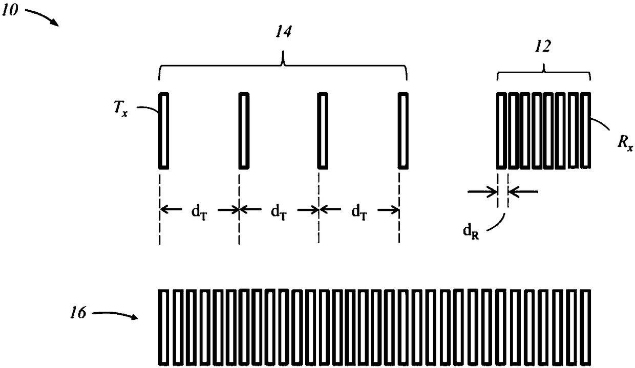
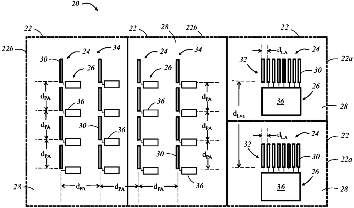
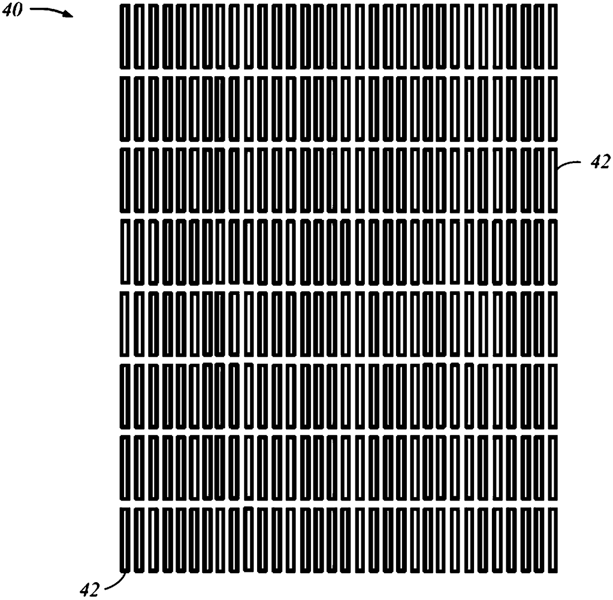
[0012] The systems and methods described below relate to a modular and configurable MIMO antenna array architecture. In one embodiment, a modular array includes a plurality of antenna modules, each having antenna elements arranged to form a linear array or a planar array. Each antenna module also includes transmitter or receiver circuitry such that the linear and planar arrays on each board can be configured for operation as either a transmitter array or a receiver array. The staggered spacing between the antenna elements of the linear and planar arrays is selected such that the MIMO antenna array formed from the selected combination of linear and planar arrays forms a uniformly spaced virtual array.

[0013] figure 2 An exemplary architecture is shown for a MIMO antenna array 20 in accordance with at least one embodiment of the present invention. Antenna array 20 is a modular structure formed of a plurality of antenna modules 22, each antenna module having an array portion...


PUM


Abstract

A multiple input multiple output (MIMO) antenna for a radar system, the antenna for at least one first module having a plurality of antenna elements forming a linear array, wherein the plurality of antenna elements in the linear array are uniformly separated by a first distance; and for at least one second module having a plurality of antenna elements forming a planar array, wherein the pluralityof antenna elements in the planar array are uniformly separated by a second distance; and wherein the at least one first module and the at least one second module are selectively configured to function as transmitter modules or receiver modules, and wherein an interleaving between the plurality of antenna elements in the linear array of the at least one first module with the plurality of antenna elements in the planar array of the at least one second module produces a uniform virtual antenna array.

Description

technical field [0001] The present invention relates generally to multiple-input multiple-output (MIMO) antenna arrays, and more particularly to modular and configurable MIMO antenna array architectures. Background technique [0002] Advanced radar systems in use today use the multiple-input multiple-output (MIMO) concept, which employs multiple antennas at the transmitter to transmit independent (orthogonal) waveforms and multiple antennas at the receiver to receive the radar returns . In a "parallel" MIMO radar configuration, the antennas in the transmitter and receiver are spaced close enough so that each antenna observes the same aspect of the target so that a point target is assumed. In MIMO receivers, matched filter banks are used to extract quadrature waveform components. When orthogonal signals are emitted from different antennas, the echoes of each signal carry independent information about the detected object and the different propagation paths. The phase differ...

Claims


Application Information

Patent Timeline
Patent Type & Authority Applications(China)
IPC IPC(8): H01Q21/00H01Q21/06H01Q21/12H01Q23/00H01Q1/32
CPCH01Q1/3233H01Q21/00H01Q21/061H01Q21/12H01Q23/00H01Q21/0025G01S13/42G01S13/931G01S13/02H01Q1/38
Inventor D·拉斐尔里I·比莱克O·比尔勒
Owner GM GLOBAL TECH OPERATIONS LLC
Why Eureka
Try Eureka