Locking mechanism of backrest-seat synchronous linkage device for office chair

A locking mechanism and synchronous linkage technology, applied in the field of office chairs and swivel chairs, can solve the problems of unfavorable base structure simplification and weight reduction, excessive occupation of the interior space of the base, inconvenient installation, etc., achieving simple structure, low cost, and reduced height. Effect

Pending Publication Date: 2019-03-05
UE FURNITURE CO LTD
View PDF4 Cites 0 Cited by
  • Summary
  • Abstract
  • Description
  • Claims
  • Application Information

AI Technical Summary

Problems solved by technology

[0010] But some people wish to lock the back of the chair in a comfortable position for taking a lunch break or a long rest, so it is necessary to design a locking mechanism with simple structure, low cost and no space occupation; the applicant's The previous patents "CN201410479184.4-seat back rocker locking mechanism for swivel chair chassis" and "CN201310438112.0-chair back rocker locking mechanism" are relatively complicated in structure, occupying too much internal space of the base, and installation is also difficult. Inconvenient, not conducive to the simplification and weight reduction of the base structure

Method used


Image

  • Locking mechanism of backrest-seat synchronous linkage device for office chair
  • Locking mechanism of backrest-seat synchronous linkage device for office chair
  • Locking mechanism of backrest-seat synchronous linkage device for office chair

Examples


Embodiment 1

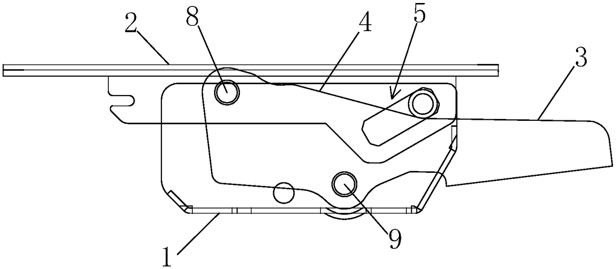
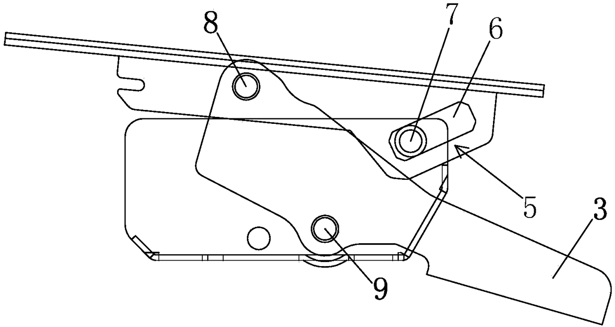
[0055] Embodiment 1: first define the reference orientation of each part of the present invention, the present invention is when office chair is installed normally, and the front of office chair is front end, front part, and the rear of office chair comprises the position of chair back, seesaw where is Rear end, rear.

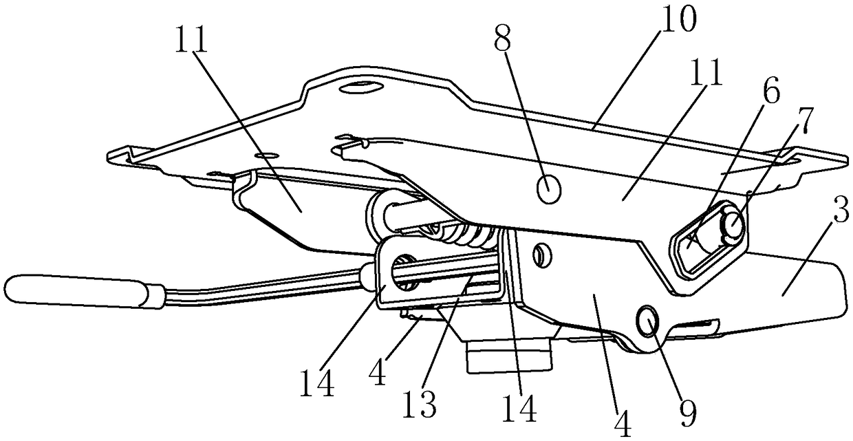
[0056] The synchronous linkage device for the back seat of the office chair of the present embodiment, such as Figure 1 to Figure 14 As shown, it includes a base 1, a bracket 2 for connecting the seat, a seesaw 3 for connecting the back of the chair, and at least one crank 4. The upper and lower ends of the crank 4 are respectively hinged with the front of the bracket 2 and the base 1. The crank 4 is arranged obliquely, and the seesaw 3 and the crank 4 are connected as a whole. It can also be said that the seesaw 3 and the crank 4 are integrally formed; The chute guide mechanism 5 for lifting guidance; when the seesaw 3 rotates to a larger or smaller inclinat...

Embodiment 2

[0064] Example 2: Figure 15 , 16 A base structure of the device of the present invention is illustrated, the base 1 includes a base plate 13 and side plates 14 extending upward along both sides of the base plate 13, the hinge point 41 between the lower end of the crank 4 and the base 1 is at the lower end of the side plate 14, for To meet the inclination of the crank, the height of the side plate 14 is more than 8CM; and the sleeve 44 for inserting the support rod is arranged in the base, and is reinforced by the cuboid reinforcement seat 47 surrounding the sleeve 44 in the base, but This may make the height and weight of the main body of the base 1 too large, which is not conducive to the development towards the direction of weight reduction.

[0065] Figure 17 , 18 An improved base structure is shown. The base 1 also includes a base plate 13 and side plates 14 extending upward along both sides of the base plate 13. The overall height of the side plates 14 is 3.5-4.5 cm....

Embodiment 3

[0068] Embodiment 3: as Figure 21 , 22 As shown, in this embodiment, no connection plate is provided on the bottom surface of the base 1, and the lug 43 is integrally formed with the bottom plate 13 or the side plate 14; A part cut out is bent downward; other technical solutions are the same as in embodiment 2.


PUM


Abstract

The invention discloses a locking mechanism of a backrest-seat synchronous linkage device for an office chair. The locking mechanism comprises a base and two cranks, the base comprises a bottom plateand side plates extending along two sides of the bottom plate, and the cranks are arranged on outer sides of the two side plates respectively. The locking mechanism further comprises a lock pin and acontrol rod. One of the side plates is provided with a second through hole, the lock pin penetrates the second through hole, and a position, close to the second through hole, of the lock pin is provided with a lock bolt in a radial extending manner. The second through hole is communicated with a positioning hole matched with the lock bolt, and the crank close to the second through hole is providedwith a clamping groove matched with the lock bolt. In an initial state, the lock pin is moved through the control rod, and the lock bolt is inserted into the positioning hole and the clamping grooveof the other crank at the same time to realize locking; in a lifting state of a seat, the lock pin is moved through the control rod, the end of the lock bolt is inserted into the positioning hole, andthen, the lower edge of the crank close to the second through hole is lapped on the lock bolt of the lock pin to realize locking in the lifting state. The locking mechanism of the backrest-seat synchronous linkage device for the office chair has advantages of simple structure, low cost and convenience in operation.

Description

technical field [0001] The invention relates to the technical field of swivel chairs and office chairs, in particular to a locking mechanism for a synchronous linkage device for the back seat of an office chair. Background technique [0002] In the prior art, there is a linkage device for synchronizing the seat and the back of the chair. When the back of the chair is reclined, the seat moves. synchronization device. Wherein the four-bar link mechanism includes two cranks, one in front and the other in back. The crank is hinged between the seat frame and the chair base, wherein the seat frame is integrated with the rear crank of the four-bar linkage. [0003] The front crank and the rear crank are inclined in different directions with respect to the same vertical, i.e. if the front crank is inclined at an acute counterclockwise direction with respect to the vertical, the rear crank is inclined clockwise with respect to the vertical Directions are inclined at acute angles; ...

Claims


Application Information

Patent Timeline
Patent Type & Authority Applications(China)
IPC IPC(8): A47C1/032A47C7/00
CPCA47C1/0325A47C1/03255A47C7/00
Inventor 何基叶金金明华
Owner UE FURNITURE CO LTD
Why Eureka
Try Eureka