Control for an Automatic Transmission

a technology of automatic transmission and control panel, which is applied in the direction of mechanical equipment, propulsion parts, transportation and packaging, etc., can solve the problems of increasing cost and size, delay, and delay temperature sensitive, and achieves the reduction of delay and sensitivities, reducing valve body height, and small space

Active Publication Date: 2011-03-24
FORD GLOBAL TECH LLC
View PDF21 Cites 0 Cited by
  • Summary
  • Abstract
  • Description
  • Claims
  • Application Information

AI Technical Summary

Benefits of technology

[0011]The control system allows the valve body to have two layers rather than the conventional four layers, thereby reduce the valve body height by about 30 mm compared to conventional valve body configurations, permitting it to be packaged in a smaller space.
[0012]By removing the regulator valve, delays and sensitivities are reduced such that the period required to perform a gear changes is are shortened to about 150 Ms.
[0013]The number of valves in the control system is reduced from about 14 to about eight. This reduction combined with the reduction of two valve bodies offsets the cost of additional solenoids, producing a net cost reduction for the entire electro-hydraulic control assembly.

Problems solved by technology

Such a valve body adds cost and size due to the many valve body layers, and it creates hydraulic response time delays due to the multiple stages from solenoid output to regulator valve input to regulator output, which must be controlled.
Further, these delays are temperature sensitive.
Conventional automatic transmissions use bleed flows to improve the hydraulic controls performance and repeatability, but these flows result in lost hydraulic power, which power loss is detrimental to fuel economy.
Variable displacement pump controls are indirectly controlled, which can introduce system instability and deliver a fluid flow rate that is much higher than needed by the transmission, further reducing fuel economy.
A conventional one-way-clutch is costly and creates internal drag in the transmission.

Method used


Image

  • Control for an Automatic Transmission
  • Control for an Automatic Transmission
  • Control for an Automatic Transmission

Examples


Embodiment Construction

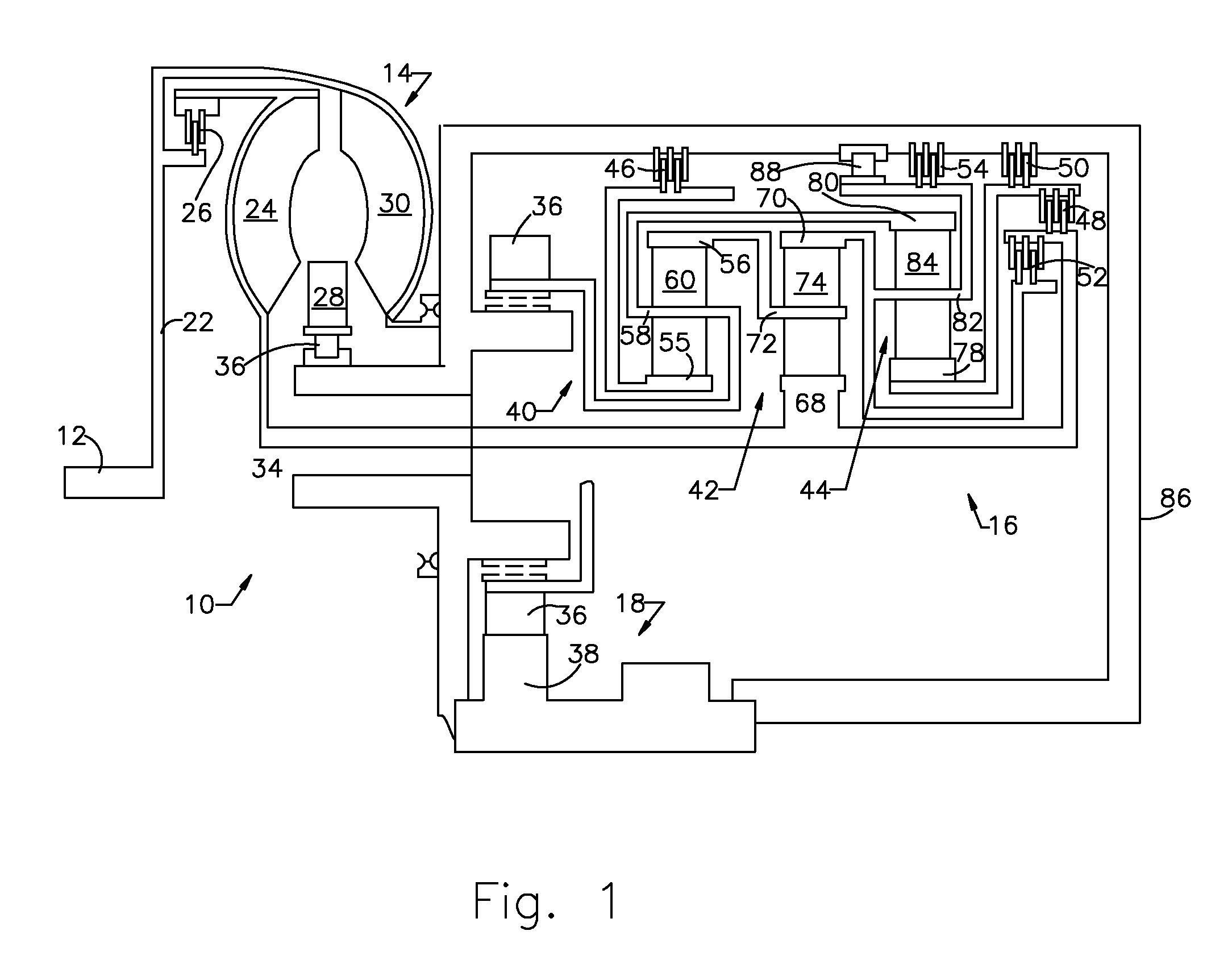
[0021]Referring now to the drawings, there is illustrated in FIG. 1 the powertrain 10 for a motor vehicle, which includes an engine 12, torque converter 14, transmission 16, and an output drive mechanism 18. The engine 12 is an internal combustion engine well known to those skilled in the art. The torque converter 14 includes having an impeller 30 connected through an input shell and flex plate 22 with the crankshaft of the engine 12, a turbine 24, friction clutch 26, and a stator 28, which is grounded through a one-way clutch 36. The turbine 24 and clutch 26 are driveably connected to a transmission input shaft 34. The output drive mechanism 18 includes meshing output gears 36 and 38.

[0022]The transmission 16 includes three planetary gearsets 40, 42, 44, and five friction control elements, which are torque-transmitting clutches and brakes 46, 48, 50, 52, and 54.

[0023]Gearset 40 includes a sun gear 55, ring gear 56, and planet carrier 58, which is comprised of a plurality of planet ...


PUM


Abstract

A system for controlling a transmission includes a gear selector, a manual valve for connecting a pressure source alternately to Drive and Reverse lines in response to movement of the gear selector between selected Drive and Reverse positions, first and second solenoid-actuated valves, the first valve connecting the pressure source to a first control element, the second valve connecting the Reverse line to a second control element when the Reverse position is selected, a third solenoid-actuated valve connecting the Drive line to a third control element when the Drive position is selected, and a control valve through which pressure in the first control element is vented when the Drive position is selected.

Description

BACKGROUND OF THE INVENTION[0001]1. Field of the Invention[0002]This invention relates generally to controlling an automatic transmission, particularly to a system having direct electronic shift control.[0003]2. Description of the Prior Art[0004]Most current automatic transmissions use a solenoid in conjunction with a regulator & latch valve to control independently the clutches and brakes, which are applied and released to produce the transmission gear ratios. A valve body assembly that includes a solenoid with a regulator & latch valve for this purpose requires many layers to accommodate all of the solenoids and valves. Such a valve body adds cost and size due to the many valve body layers, and it creates hydraulic response time delays due to the multiple stages from solenoid output to regulator valve input to regulator output, which must be controlled. Further, these delays are temperature sensitive.[0005]Conventional automatic transmissions use bleed flows to improve the hydraul...

Claims


Application Information

Patent Timeline
Patent Type & Authority Applications(United States)
IPC IPC(8): F16H61/30
CPCF16H61/0206Y10T74/20024F16H2312/09F16H61/0286
Inventor FRAIT, STEVE A.
Owner FORD GLOBAL TECH LLC
Why Eureka
Try Eureka