Cooking utensil

A technology for cooking utensils and components, which is applied to steam cooking utensils, the structure of cooking utensils, cooking utensils, etc., can solve problems such as affecting the cooking process, collision friction, damage to driving devices, etc. The effect of stability

Pending Publication Date: 2019-03-05
FOSHAN SHUNDE MIDEA ELECTRICAL HEATING APPLIANCES MFG CO LTD
View PDF0 Cites 6 Cited by
  • Summary
  • Abstract
  • Description
  • Claims
  • Application Information

AI Technical Summary

Problems solved by technology

[0002] At present, existing intelligent cooking appliances such as automatic electric rice cookers have the function of washing rice in the inner pot. The driving device drives the cleaning component to move down to the cleaning material in the inner pot to realize the cleaning function. After cleaning, the driving device drives the cleaning component upwards. Movement reset; and in the process of reciprocating up and down, if the cleaning component moves downward or upward excessively, it will collide with the inner pot or the upper cover, and even cause damage to the driving device, and if the downward movement is not in place, it will affect the cleaning effect, improper upward movement can affect the cooking process or produce other adverse effects

Method used


Image

  • Cooking utensil
  • Cooking utensil

Examples


Embodiment 1

[0068] Embodiment one (as figure 1 and figure 2 shown)

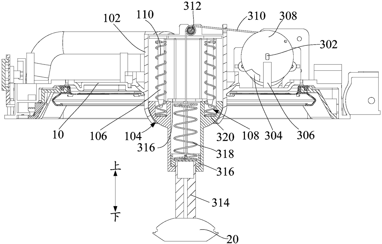
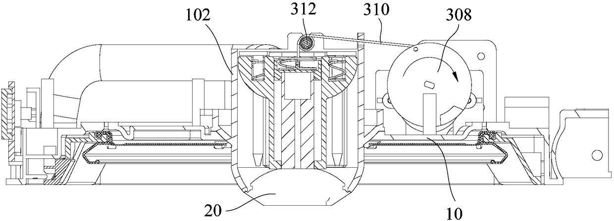
[0069] The stroke control device includes: a first limiter and a second limiter, the first limiter is fixedly connected with the rotating member; the second limiter is fixedly connected with the upper cover 10, and can move to the first position when the cleaning assembly 20 And when it moves to the second position, it interferes with the first limiting member, so as to restrict the rotating member from continuing to rotate, so that the driving device stops running.

[0070] The stroke control device includes a first limiter and a second limiter. The first limiter is fixed on the rotating member and rotates synchronously with the rotating member. The second limiter is fixedly connected with the upper cover 10 and kept relative to the rotating member. Stationary; when the cleaning assembly 20 moves to the first position and to the second position, the second limiting member interferes with the first limiting member (fo...

Embodiment 2

[0081] Embodiment 2 (not shown in the figure)

[0082] The difference from Embodiment 1 is that one of the first limiting member and the second limiting member is an arc-shaped chute, and the other is a protruding post matching the arc-shaped chute, and the protruding post is inserted into the arc-shaped chute and can slide in the arc-shaped chute, wherein, when the cleaning assembly 20 moves to the first position and to the second position, the boss moves to the end of the arc-shaped chute to interfere with the arc-shaped chute .

[0083] This embodiment utilizes the cooperation of the arc-shaped chute and the convex post to make the radian of the arc-shaped chute equal to the rotation angle of the rotating part. The arc chute interferes, which restricts the rotating part from continuing to rotate.

Embodiment 3

[0084] Embodiment three (not shown in the figure)

[0085] The travel control device includes: a trigger and a travel switch, the trigger is arranged on the rotating part; the travel switch is installed on the upper cover 10, and is electrically connected with the electric control board; wherein, when the cleaning assembly 20 moves to the first position and moves to At the second position, the trigger member triggers the travel switch, so that the electric control board controls the driving member to stop running.

[0086] The trigger part is arranged on the rotating part and rotates together with the rotating part; the travel switch is installed on the upper cover 10, remains stationary, and is electrically connected with the electric control board, when the cleaning assembly 20 moves to the first position and moves to the second position , the travel switch is triggered by the trigger, and then generates an electric signal to the electric control board, and the electric cont...


PUM


Abstract

The invention provides a cooking utensil. The cooking utensil includes an upper cover, an inner pot, a cleaning assembly, and a stroke control device; the inner pot is located below the upper cover and used for carrying water and materials; the cleaning assembly can reciprocate between a first position and a second position that are between the upper cover and the inner pot; a driving device is connected to the cleaning assembly and used for driving the cleaning assembly to reciprocate; and the stroke control device is connected to the driving device and can make the driving device stop running when the cleaning assembly moves to the first position and to the second position to control a movement stroke of the cleaning assembly. The cooking utensil is additionally provided with the strokecontrol device, so that the time of stopping the operation of the driving device is accurately corresponding to an endpoint position of the movement stroke of the cleaning assembly, thereby ensuring that the cleaning assembly can accurately move to the first position and the second position, and various adverse effects caused by excessive movement or improper movement of the cleaning assembly in the prior art are effectively avoided, and the usage reliability and safety of a product are improved.

Description

technical field [0001] The invention relates to the technical field of kitchen appliances, in particular to a cooking utensil. Background technique [0002] At present, existing intelligent cooking appliances such as automatic electric rice cookers have the function of washing rice in the inner pot. The driving device drives the cleaning component to move down to the cleaning material in the inner pot to realize the cleaning function. After cleaning, the driving device drives the cleaning component upwards. Movement reset; and in the process of reciprocating up and down, if the cleaning component moves downward or upward excessively, it will collide with the inner pot or the upper cover, and even cause damage to the driving device, and if the downward movement is not in place, it will affect the cleaning Effect, improper upward movement will affect the cooking process or produce other adverse effects. Therefore, how to precisely control the movement stroke of the cleaning a...

Claims


Application Information

Patent Timeline
Patent Type & Authority Applications(China)
IPC IPC(8): A47J27/00A47J36/00A47J27/08A47J27/04A47J31/00
CPCA47J27/002A47J27/004A47J27/04A47J27/0802A47J31/00A47J36/00
Inventor 刘小力潘典国杨保民周忠宝何柏锋
Owner FOSHAN SHUNDE MIDEA ELECTRICAL HEATING APPLIANCES MFG CO LTD
Why Eureka
Try Eureka