Display equipment supporting device and diasonograph provided with same

A technology of display equipment and support device, which is applied in the directions of sonic diagnosis, ultrasonic/sonic/infrasonic diagnosis, infrasonic diagnosis, etc., can solve the problems of difficult to make small volume, difficult assembly, large four-bar linkage structure, etc., to simplify the internal structure and assembly difficulty, labor-saving angle adjustment, and the effect of simplifying internal parts

Active Publication Date: 2019-03-05
SHENZHEN MINDRAY BIO MEDICAL ELECTRONICS CO LTD
View PDF5 Cites 4 Cited by
  • Summary
  • Abstract
  • Description
  • Claims
  • Application Information

AI Technical Summary

Problems solved by technology

[0003] At present, the volume of support arms on the market is generally relatively large. The reason is that the internal moment balance components (spring components or gas springs, etc.) of the support arms are placed obliquely, which inevitably results in a relatively large volume at one end.
There are two main types of small-sized support arms: one is that the internal moment balance components (spring components or gas springs, etc.) of the support arm are placed horizontally, but the track slider structure must be configured. , affecting the appearance of the design
The second is to use the torsion spring to cooperate with the four-link structure to achieve torque balance. In order to obtain a larger balance force, the volume of the torsion spring at the end of the torque is increased, and an additional force value compensation mechanism is required, which involves many key parts and is difficult to assemble. , the volume is difficult to make small

Method used


Image

  • Display equipment supporting device and diasonograph provided with same
  • Display equipment supporting device and diasonograph provided with same
  • Display equipment supporting device and diasonograph provided with same

Examples


Embodiment 1

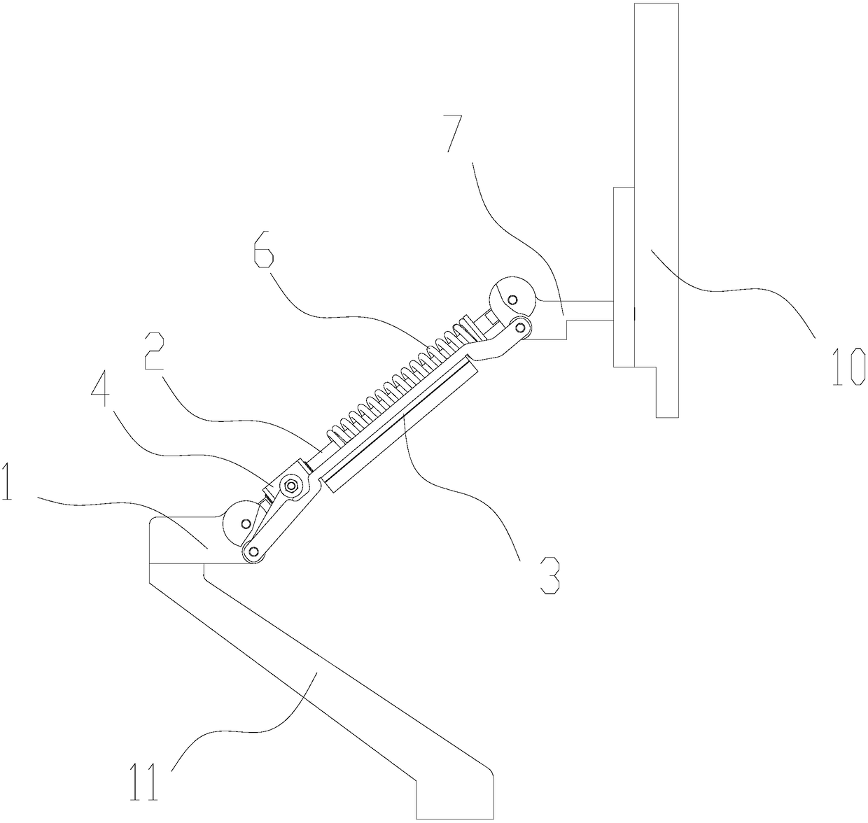
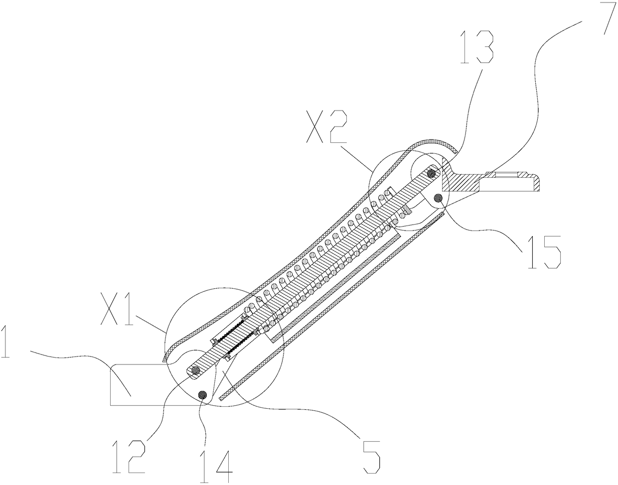
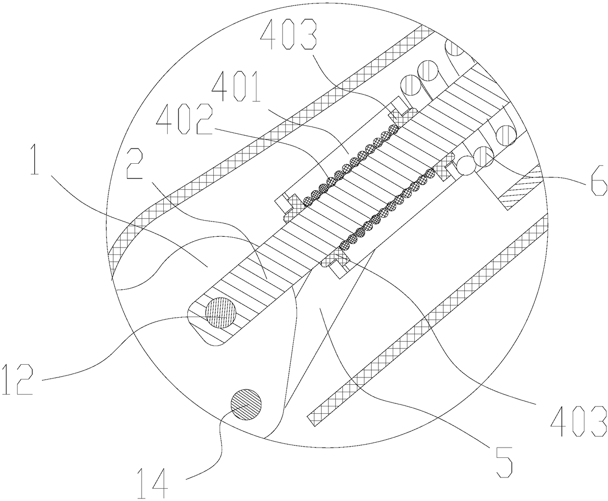
[0066] Figure 1 to Figure 10 A preferred embodiment of the display device supporting device of the present application is shown. in, figure 1 It is a schematic diagram of the structure of this display device supporting device applied to a desktop color ultrasound (a type of ultrasonic diagnostic instrument) in this embodiment. Similar to traditional desktop color Doppler ultrasound, figure 1 This desktop color ultrasound also includes a fuselage and a display device 10 (display screen), the keyboard assembly is installed on the fuselage, and the fuselage includes a lower support arm 11 protruding outwards, which can be connected with the body structure of the fuselage. It is completely fixed, and can also be rotatably connected with the body structure of the fuselage. The same as the traditional display device support device, the display device support device of this embodiment also includes a support base 1, a display connection frame 7, and a first first connecting frame...

Embodiment 2

[0093] Figure 10 with Figure 11 A second preferred embodiment of the display device supporting device of the present application is shown. This display device supporting device in this embodiment is basically the same as the structure in the above-mentioned first embodiment, the only difference is that the above-mentioned spring 6 is not provided in this embodiment, but the second support arm 3 and the display connecting frame 7 are connected in rotation A rotation damping device is provided. Therefore, the damping force generated by the rotation damping device at the rotational connection between the second support arm 3 and the display connecting frame 7 is used to reduce the static friction force between the slider 4 and the first support arm 2 .

[0094] The specific structure of the rotation damping device of this embodiment can refer to Figure 11 As shown, a compression spring is arranged outside the fourth rotating shaft 15 used to rotatably connect the second sup...

Embodiment 3

[0098] Figure 12 with Figure 13 A third preferred embodiment of the display device supporting device of the present application is shown. The display device support device in this embodiment is basically the same as the structure in the first embodiment above, the only difference is:

[0099] In this embodiment, the structure of the friction sleeve 502 is canceled, so that the original slider can slide freely on the first support arm 2, and the damping function between the original slider and the first support arm 2 is cancelled. description, and for the convenience of readers’ understanding, we call this embodiment of the slider that no longer has a damping function slider II (in Figure 12 Among them, its reference number is 9).

[0100] At the same time, in this embodiment, a rotation damping device is provided at the rotational connection between the second support arm 3 and the display connecting frame 7 . Therefore, the synergistic effect of the rotation damping de...


PUM


Abstract

The invention discloses a display equipment supporting device and a diasonograph provided with the same. The display equipment supporting device comprises a supporting substrate, a displayer connecting rack, a connecting arm and a first supporting arm; the two ends of the first supporting arm are correspondingly rotationally connected with the supporting substrate and the displayer connecting rack; a slider which is in friction fit with the first supporting arm is arranged on the first supporting arm in a sleeving manner; the two ends of the connecting arm are correspondingly rotationally connected with the slider and the supporting substrate; the rotary joint of the connecting arm and the supporting substrate is positioned at a first position; and the rotary joint of the first supportingarm and the supporting substrate is positioned at a second position. The display equipment supporting device disclosed by the invention is simple and compact in structure, light and small in appearance, low in manufacturing cost, capable of stably supporting display equipment at any position and high in performance-cost ratio.

Description

technical field [0001] The present application relates to a display device supporting device, in particular to a display device supporting device for an ultrasonic diagnostic instrument and an ultrasonic diagnostic instrument configured with such a device. Background technique [0002] In recent years, ultrasonic diagnostic instruments tend to be portable and miniaturized. As the main component, the monitor support arm also has the design requirements of small volume and light appearance. [0003] At present, the volume of support arms on the market is generally relatively large. The reason is that the internal moment balance components (spring components or gas springs, etc.) of the support arms are placed obliquely, which inevitably results in a relatively large volume at one end. There are two main types of small-sized support arms: one is that the internal moment balance components (spring components or gas springs, etc.) of the support arm are placed horizontally, but t...

Claims


Application Information

Patent Timeline
Patent Type & Authority Applications(China)
IPC IPC(8): F16M11/04F16M11/12F16M11/16A61B8/00
CPCF16M11/04F16M11/121F16M11/16A61B8/44A61B8/46
Inventor 杨荣富赵彦群陈志武
Owner SHENZHEN MINDRAY BIO MEDICAL ELECTRONICS CO LTD
Why Eureka
Try Eureka