Light-emitting casing

A technology of housing and light-emitting unit, which is applied to semiconductor devices, light sources, plane light sources, etc. of light-emitting elements, can solve the problems of increasing the number and thickness of components in the housing and increasing the number of LED light bars.

Inactive Publication Date: 2019-03-05
PEGATRON
View PDF9 Cites 0 Cited by
  • Summary
  • Abstract
  • Description
  • Claims
  • Application Information

AI Technical Summary

Problems solved by technology

[0003] In terms of setting, it is mostly used to generate the desired pattern in the form of a light-transmitting area on the housing, and then set LED light strips at the corresponding positions in the housing and arrange them in the area to be illuminated, so that the required LED lights The number of strips increases, and the LED light strip has a certain thickness. After using the LED light strip group, the number and thickness of the components in the shell will increase.

Method used


Image

  • Light-emitting casing
  • Light-emitting casing
  • Light-emitting casing

Examples


Embodiment Construction

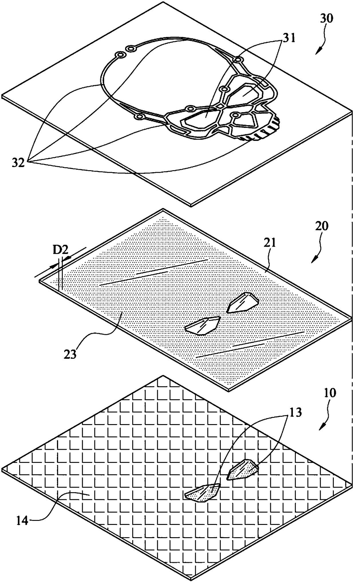
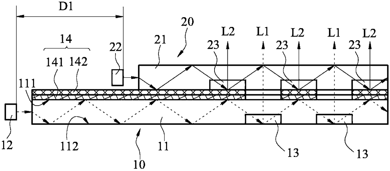
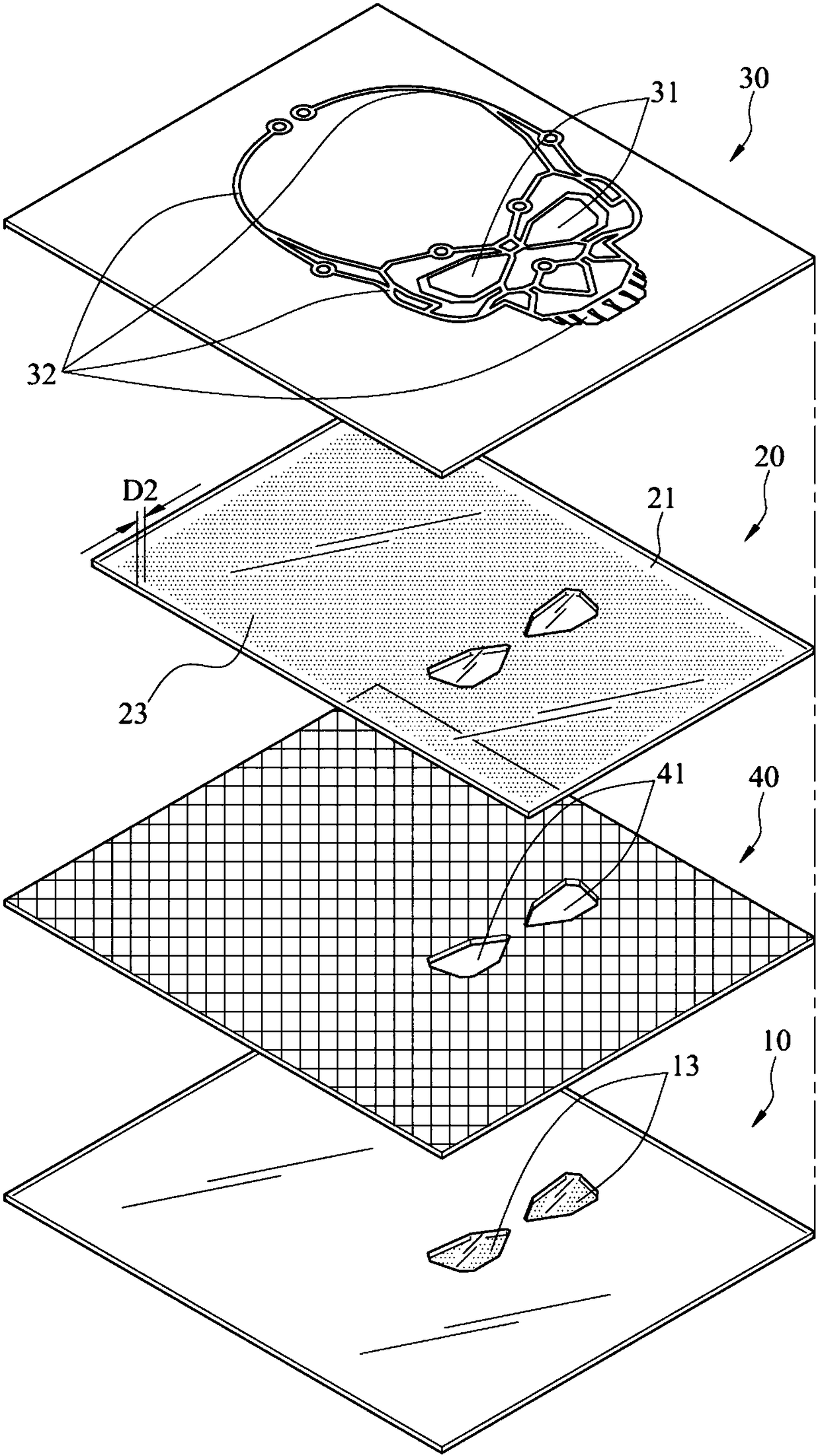
[0025] Please also see figure 1 and figure 2 , figure 1 It is an exploded view of the first embodiment of the light-emitting housing of the present invention, figure 2 It is a partial sectional view of this embodiment. Such as figure 1 As shown, the light-emitting housing of this embodiment includes a first light-emitting module 10 , a second light-emitting module 20 , a shield and a housing 30 . The second light emitting module 20 is disposed above the first light emitting module 10 , the shielding member is disposed between the first light emitting module 10 and the second light emitting module 20 , and the housing 30 is further disposed above the second light emitting module 20 . exist figure 2 The uppermost housing 30 is omitted. The casing 30 can be a casing of any electronic component, such as a display screen, a laptop, or a tablet, and its size and shape are not limited. The casing shown in this embodiment is only an example.

[0026] Such as figure 1 As sho...


PUM


Abstract

The invention provides a light-emitting casing. The light-emitting casing comprises a first light-emitting module, a second light-emitting module, a shielding piece and a casing; the first light-emitting module comprises a first light guiding plate and a first light-emitting unit; multiple first lattice point areas are arranged on the first light guiding plate; the first light-emitting unit provides first light which is emitted to the first light guiding plate; the second light-emitting module comprises a second light guiding plate and a second light-emitting unit; the second light guiding plate is arranged above the first light-emitting module; multiple second lattice point areas are arranged on the second light guiding plate; the arrangement range of the second lattice point areas is notoverlapped with that of the first lattice point areas; the second light-emitting unit provides second light which is emitted to the second light guiding plate; the shielding piece is arranged betweenthe first light-emitting module and the second light-emitting module and is not overlapped with the first lattice point areas; and the casing is arranged above the second light-emitting module and comprises first light transmitting areas and second light transmitting areas.

Description

technical field [0001] The invention relates to a luminous housing, in particular to a luminous housing capable of emitting different color patterns. Background technique [0002] In the prior art, in order to make the shell more beautiful and increase the attractiveness of consumers to buy, patterns are arranged on the shell, and the light source is irradiated from the inside to the outside, so that the pattern is eye-catching. [0003] In terms of setting, it is mostly used to generate the desired pattern in the form of a light-transmitting area on the housing, and then set LED light strips at the corresponding positions in the housing and arrange them in the area to be illuminated, so that the required LED lights The number of strips increases, and the LED light strip has a certain thickness. After the LED light strip is used, the number and thickness of the components in the housing will increase. Contents of the invention [0004] An embodiment of the present inventi...

Claims


Application Information

Patent Timeline
IPC IPC(8): F21K9/20F21K9/61F21K9/66F21Y105/10F21Y115/10
CPCF21K9/20F21K9/61F21K9/66F21Y2105/10F21Y2115/10
Inventor 林雨德陈贤隆王智勇陈信福
Owner PEGATRON
Why Eureka
Try Eureka