Thermal barrier structure for energy-saving renovation of existing building envelope

An envelope structure and existing building technology, applied in building structures, building components, buildings, etc., can solve the problems of building space occupation and the use of cement mortar soaring, increase the overall thickness, avoid use waste, and transport The effect of dimension difficulty and workload reduction

Active Publication Date: 2022-02-18
ANHUI UNIVERSITY OF ARCHITECTURE
View PDF4 Cites 0 Cited by
  • Summary
  • Abstract
  • Description
  • Claims
  • Application Information

AI Technical Summary

Problems solved by technology

Theoretically, the construction method of embedding a non-load-bearing layer is suitable for both new buildings and existing buildings, but no matter whether it is embedded in the inner plaster layer or the construction method of embedding the cement mortar layer between the load-bearing layer and the outer insulation layer, there will be additional Increasing the overall thickness of the envelope structure leads to a surge in the use of cement mortar and a large amount of building use space. Therefore, this construction method offsets the advantages of "material saving" and "slimming" of the thermal barrier structure to a certain extent.

Method used


Image

  • Thermal barrier structure for energy-saving renovation of existing building envelope
  • Thermal barrier structure for energy-saving renovation of existing building envelope
  • Thermal barrier structure for energy-saving renovation of existing building envelope

Examples


Embodiment Construction

[0027] The present invention will be described in detail below in conjunction with the accompanying drawings and specific embodiments.

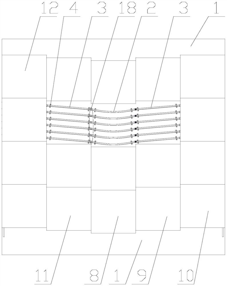
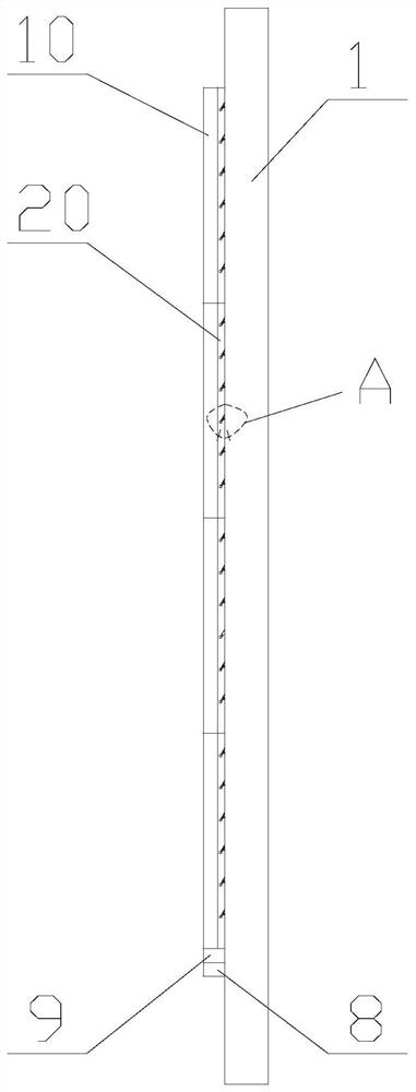
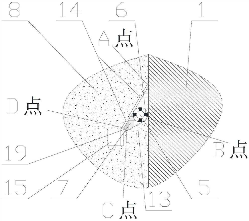
[0028] In the present invention, the thermal barrier structure used for energy-saving renovation of the existing building envelope structure is as follows: Figure 1-Figure 8b As shown, it consists of a wall base 1, a plurality of heat exchange pipelines and an outer insulation layer of an enclosure structure. The plurality of heat exchange pipelines are installed on the outer side of the wall base through the fixed sleeve fittings 4 and are covered by insulation boards. The same type of insulation boards are arranged in the same vertical direction, and the row of insulation boards in the middle is the last At the bottom, the insulation boards on both sides are staggered upward column by column. This staggered arrangement is passively caused, not artificially intended to be arranged in staggered layers. Because the fixed casing grooves in ea...


PUM


Abstract

The invention discloses a thermal barrier structure for energy-saving renovation and renovation of an existing building envelope structure, which comprises a wall base, a plurality of heat exchange pipelines and a plurality of insulation boards, and the plurality of heat exchange pipelines are installed on the base of the wall body The outer side is covered by insulation boards. The same type of insulation boards are arranged in the same vertical direction. The middle row of insulation boards is at the bottom. The insulation boards on both sides are staggered upward one by one. Multiple heat exchange pipes include fixed sleeves. Pipe, fluid pipe and heat conduction fixed layer, the fluid pipe is fixed in the fixed sleeve through the pipe positioning card, the heat conduction fixed layer is filled between the fixed sleeve and the fluid pipe, and the inner surfaces of multiple insulation boards are respectively provided with fixed sleeve grooves, fixed The sleeve is located in the fixed sleeve groove. The application of this thermal barrier structure in existing buildings will not have a substantial impact on the structural safety of the envelope itself, and can effectively improve the thermal insulation performance of existing buildings while greatly reducing the space occupation and building materials of the thermal barrier structure. Dosage.

Description

technical field [0001] The invention relates to the technical field of building energy conservation and renovation, in particular to a thermal barrier structure for energy conservation renovation of an existing building envelope. Background technique [0002] Thermal barrier is a new type of building thermal insulation technology. By embedding fluid pipes in the load-bearing layer of the building envelope or the plastering layer on the inner and outer surfaces and injecting low-grade natural energy or renewable energy, this technology can be used in the building envelope. A virtual thermal insulation interface is formed in the middle, that is, a thermal barrier, so as to achieve the technical effect of actively blocking the heat transfer between indoor and outdoor. However, the current engineering application of this technology is still mainly limited to new buildings, and this technology is rarely used in the energy-saving renovation of existing buildings, because it is usu...

Claims


Application Information

Patent Timeline
Patent Type & Authority Patents(China)
IPC IPC(8): E04G23/02E04B1/78
CPCE04G23/02E04B1/78
Inventor 陈萨如拉钟杰张笑笑杨洋常甜馨
Owner ANHUI UNIVERSITY OF ARCHITECTURE
Why Eureka
Try Eureka