Geothermal energy heat exchange device

A heat exchange device and geothermal energy technology, applied in geothermal energy, geothermal collectors, heat pumps, etc., to achieve low production costs and operating costs, sustainable mining, and good heat exchange effects

Inactive Publication Date: 2019-03-05
XIAN GAIWO THERMAL ENERGY TECH
View PDF0 Cites 0 Cited by
  • Summary
  • Abstract
  • Description
  • Claims
  • Application Information

AI Technical Summary

Problems solved by technology

The present invention can solve two problems in the background technology, so as to obtain heat without taking water, and not cause environmental problems

Method used


Image

  • Geothermal energy heat exchange device
  • Geothermal energy heat exchange device

Examples


Embodiment 1

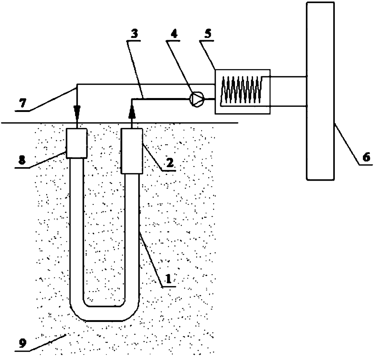
[0019] Embodiment 1: A kind of geothermal energy heat exchange device, as attached figure 1 Shown: including U-shaped heat exchanger 1, output pipe insulation section 2, output pipe 3, power pump 4, heat pump heat exchanger 5, terminal 6, return pipe 7, return pipe insulation section 8 and heat storage rock formation 9. Drill two boreholes with a diameter of 100-200mm into the heat storage rock formation by a drilling rig, and connect the two holes through directional drilling technology. The U-shaped heat exchanger 1 is arranged in the heat storage rock formation 9, and the U-shaped heat exchanger 1 Fill the circulating medium required for heat exchange, the U-shaped heat exchanger 1 is connected to the output pipe 3 and the return pipe 7 respectively, and the output pipe 3 and the return pipe 7 are wrapped with thermal insulation material 2, and the return pipe 7 is underground There is a return pipe insulation section 8, the U-shaped heat exchanger 1 is connected to the pow...

Embodiment 2

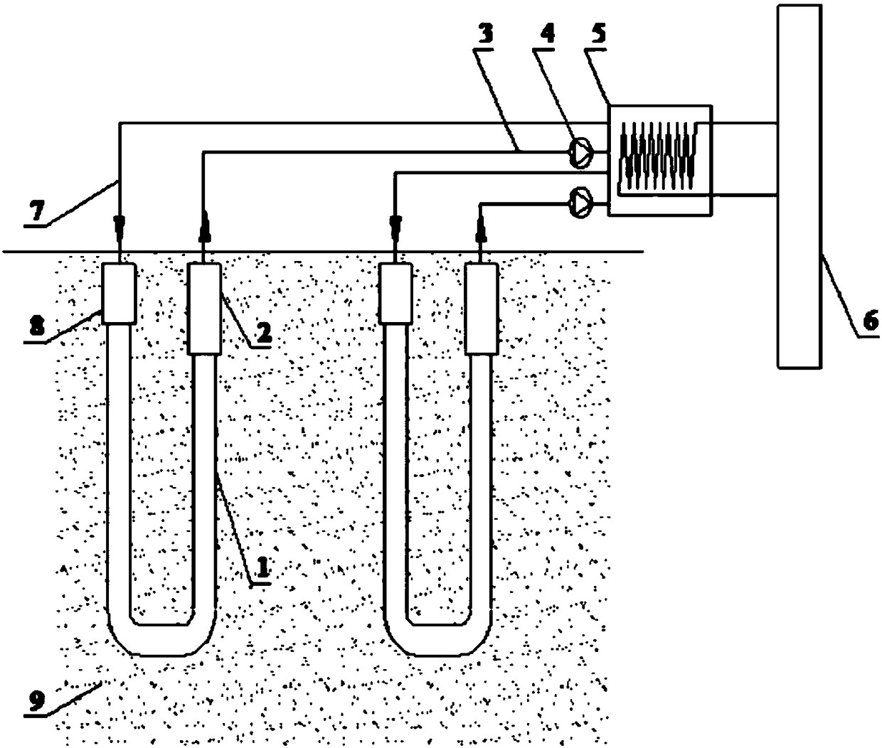
[0024] Example 2: If the heat load is large, it is necessary to arrange multiple sets of U-shaped heat exchangers in parallel. Take the arrangement of two sets of U-shaped heat exchangers as an example, as shown in the attached figure 2 Shown: including U-shaped heat exchanger 1 and 10, output pipe insulation section 2 and 14, output pipe 3 and 11, power pump 4 and 15, heat pump heat exchanger 5, end 6, return pipe 7 and 12, return pipe Insulation section 8 and 13, thermal storage rock formation 9. Drill four boreholes with a diameter of 100-200 mm into the heat storage rock layer by drilling rig, connect the two holes through directional drilling technology, connect the two holes through directional drilling technology, and lay U-shaped heat exchanger 1 on the heat storage rock layer In 9, the U-shaped heat exchanger 1 is filled with the circulating medium required for heat exchange, and the U-shaped heat exchanger 1 is connected to the output pipe 3 and the return pipe 7 re...


PUM


Abstract

The invention relates to a geothermal energy heat exchange device which comprises U-shaped heat exchangers, an output pipe, a power pump, a heat pump heat exchanger, a tail end, a return pipe and a heat storage rock stratum. One or more sets of U-shaped heat exchangers are arranged in the heat storage rock stratum. The U-shaped heat exchangers are filled with circulating media needed by heat exchange. The U-shaped heat exchangers are connected with the output pipe and the return pipe and are connected to the power pump and the heat pump heat exchanger through the output pipe. The heat pump heat exchanger is connected with the tail end. The heat pump heat exchanger is connected to the U-shaped heat exchangers through the return pipe. The temperature of the circulating media in the U-shapedheat exchangers rises in the heat exchangers, energy of the rock stratum and hot water is absorbed, the heat energy is conveyed to the heat pump heat exchanger, and the low-temperature circulating media return to the U-shaped heat exchangers after heat exchange is completed. Reciprocating circulation is carried out, and the heat energy can be developed with low cost, high efficiency and environmental friendliness. The geothermal energy heat exchange device is a novel heat exchange system which improves the geothermal utilization efficiency.

Description

technical field [0001] The invention relates to a combined heat exchange system for deep geothermal exploitation, in particular to a geothermal energy heat exchange device. Background technique [0002] Geothermal energy is natural thermal energy extracted from the earth's crust. This energy comes from the lava inside the earth and exists in the form of heat. It is a renewable energy source. According to official data released by the Ministry of Land and Resources of China, the total amount of hot dry rock resources at a depth of 3,000 meters to 10,000 meters in mainland China is equivalent to 260,000 times the total annual energy consumption in China; geothermal utilization is mainly direct utilization, and the energy directly utilized is the largest The share is ground source heat pump with 49.0%, followed by bathing and swimming with 24.9%, and conventional geothermal heating with 14.4%. There are two main disadvantages in the way of direct exploitation of groundwater: o...

Claims


Application Information

Patent Timeline
Patent Type & Authority Applications(China)
IPC IPC(8): F24T10/00F25B30/06
CPCF25B30/06
Inventor 强弱
Owner XIAN GAIWO THERMAL ENERGY TECH
Why Eureka
Try Eureka