
Time-To-Digital Conversion unit, Circuit Device, Physical Quantity Measurement Apparatus, Electronic Instrument, And Vehicle

A technology of time-to-digital conversion and circuit, applied in time-to-digital converters, electrical unknown time interval measurement, devices for measuring time intervals, etc., can solve problems such as difficult oscillation, inability to obtain sufficient timing accuracy, difficulty in starting and controlling quartz oscillators, etc. , to achieve the effect of suppressing the change of resolution

Active Publication Date: 2019-03-05
SEIKO EPSON CORP
View PDF8 Cites 10 Cited by
  • Summary
  • Abstract
  • Description
  • Claims
  • Application Information

AI Technical Summary

Problems solved by technology

Therefore, the characteristics of the clock signal of the oscillator (such as temperature characteristics, process variation, jitter characteristics, etc.) may affect the timing accuracy, so that sufficient timing accuracy cannot be obtained
As an oscillator with good oscillation characteristics, for example, a crystal oscillator is considered, but it is difficult to control the startup of the crystal oscillator, so it is difficult to start oscillation at the transition timing of the first signal (or the second signal)

Method used


Image

  • Time-To-Digital Conversion unit, Circuit Device, Physical Quantity Measurement Apparatus, Electronic Instrument, And Vehicle
  • Time-To-Digital Conversion unit, Circuit Device, Physical Quantity Measurement Apparatus, Electronic Instrument, And Vehicle
  • Time-To-Digital Conversion unit, Circuit Device, Physical Quantity Measurement Apparatus, Electronic Instrument, And Vehicle

Examples


Embodiment Construction

[0054] Hereinafter, preferred embodiments of the present invention will be described in detail. In addition, the present embodiment described below does not unduly limit the content of the present invention described in the claims, and not all the configurations described in the present embodiment are essential as the solution means of the present invention.

[0055] 1. Time-to-digital conversion circuit

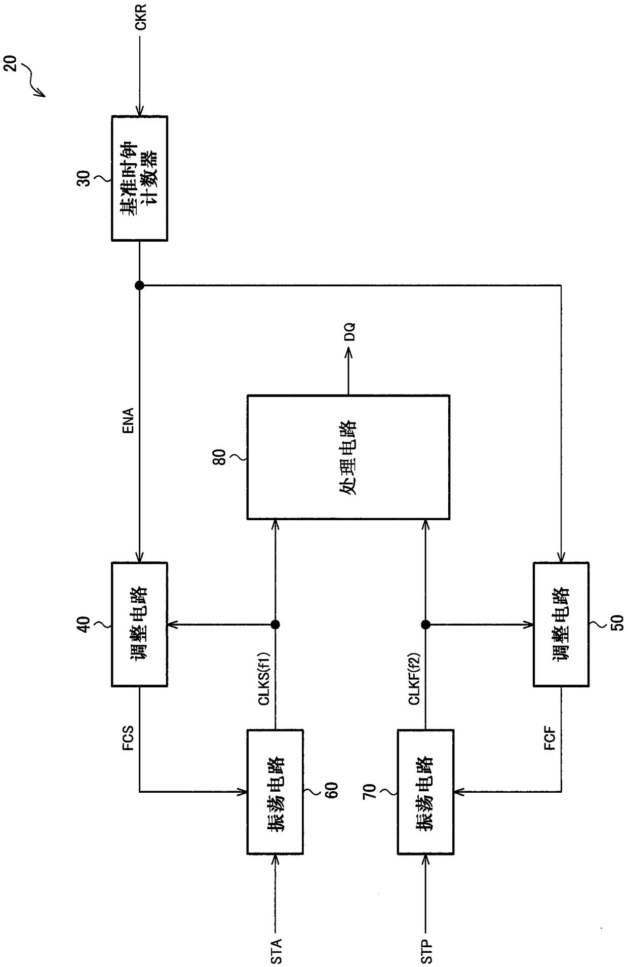
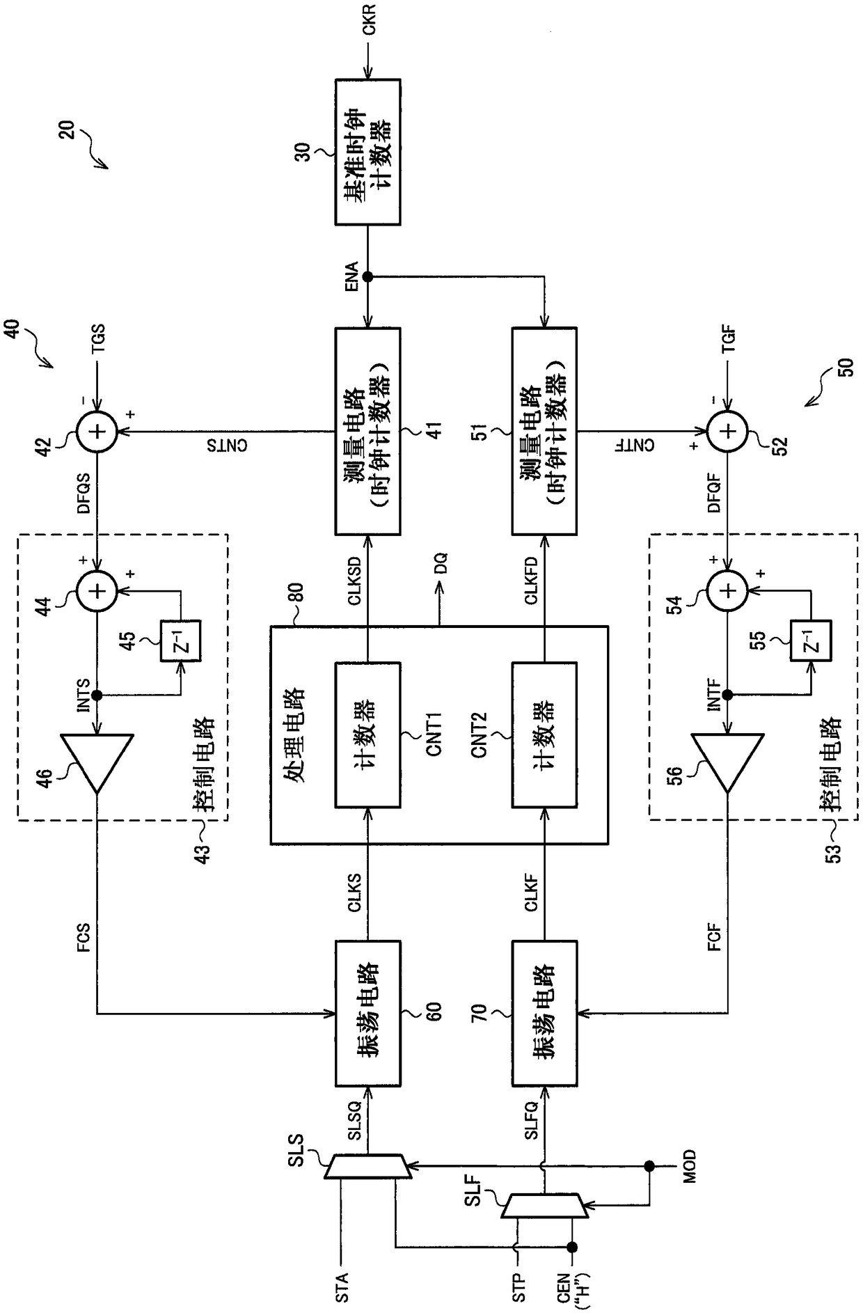
[0056] figure 1 This is a configuration example of the time-to-digital conversion circuit of this embodiment. The time-to-digital conversion circuit 20 includes an oscillation circuit 60 (first oscillation circuit), an oscillation circuit 70 (second oscillation circuit), an adjustment circuit 40 (first adjustment circuit), an adjustment circuit 50 (second adjustment circuit), and a processing circuit 80 . Furthermore, the time-to-digital conversion circuit 20 can include a reference clock counter 30 (counter). In addition, the time-to-digital conversion circuit to which t...


PUM


Abstract

The invention provides a time-to-digital conversion unit, a circuit device, a physical quantity measurement apparatus, an electronic instrument, and a vehicle, being able to realize high performance of the time-to-digital conversion circuit. The time-to-digital conversion circuit includes a first oscillation circuit that starts oscillating at the transition timing of a first signal and generates afirst clock signal having a first clock frequency, a second oscillation circuit that starts oscillating at the transition timing of a second signal and generates a second clock signal having a secondclock frequency, a first adjustment circuit that adjusts the oscillation frequency of the first oscillation circuit based on a reference clock signal, a second adjustment circuit that adjusts the oscillation frequency of the second oscillation circuit based on the reference clock signal, and a processing circuit that converts the time difference between the transition timing of the first signal and the transition timing of the second signal into a digital value based on the first and second clock signals.

Description

technical field [0001] The present invention relates to a time-to-digital conversion circuit, a circuit device, a physical quantity measuring device, electronic equipment, a mobile body, and the like. Background technique [0002] Conventionally, a time-to-digital conversion circuit for converting time into a digital value is known. As a conventional example of a time-to-digital conversion circuit that measures a time difference between a first signal and a second signal generated at an arbitrary timing, for example, a prior art disclosed in Patent Document 1 is known. [0003] Patent Document 1 discloses a timer circuit that includes: a first oscillator that starts oscillating at a frequency f in conjunction with generation of a start signal; and a second oscillator that in conjunction with generation of a stop signal Oscillation is started at frequency f+Δf, and the timing circuit compares the phase between the clock signal from the first oscillator and the clock signal f...

Claims


Application Information

Patent Timeline
Patent Type & Authority Applications(China)
IPC IPC(8): G04F10/00
CPCG04F10/005H03L7/07H03L7/0805H03L7/093H03L7/0996H03L7/23H03L2207/06B60R16/0232H03L7/0992
Inventor 须藤泰宏
Owner SEIKO EPSON CORP
Learn More